I have two units operating, one playing rigth now
But a friend is facing troubles, maybe his own errors, but more probable, the circuit may be unstable.
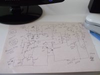
This is not oficial final schematic, it is just something to my friend to try to see if his unit works stable.
regards,
Carlos
But a friend is facing troubles, maybe his own errors, but more probable, the circuit may be unstable.
This is not oficial final schematic, it is just something to my friend to try to see if his unit works stable.
regards,
Carlos
Attachments
Last edited:
This fixed the unstability.
100n from CCS colector to ground and 100pf from CCS colector to the base.
A resistance in series, 100 ohms unit.
This will be confirmed soon, he is happy, dancing, and listening the amplifier.
regards,
Carlos
100n from CCS colector to ground and 100pf from CCS colector to the base.
A resistance in series, 100 ohms unit.
This will be confirmed soon, he is happy, dancing, and listening the amplifier.
regards,
Carlos
Attachments
Thanks Carlos and AndrewT,
That's what I suspected...may I ask a question? ...and I hope I do not divert the interest of the conversation...
Being that cap critical it seems, and being an electrolytic, would it be useful soundwise to parallel it with a bigger film cap? (bigger than 100nF; and shall I say "audiophile"?)
I have been tempted to do it myself on my DX HR II but that requires disassembling the amps to reach the bottom of the PCB and I have not had the time, occupied with DACs, as I am...
What do you think?
(C7 is also an electrolytic and "in the signal path" so to say...)
Humbly yours,
M
Originally Posted by maxlorenz:
which one would be the bootstrap cap here again?
AndrewT replied:
C10 driving R15 and the rest of the VAS stage.
That's what I suspected...may I ask a question? ...and I hope I do not divert the interest of the conversation...
Being that cap critical it seems, and being an electrolytic, would it be useful soundwise to parallel it with a bigger film cap? (bigger than 100nF; and shall I say "audiophile"?)
I have been tempted to do it myself on my DX HR II but that requires disassembling the amps to reach the bottom of the PCB and I have not had the time, occupied with DACs, as I am...
What do you think?
(C7 is also an electrolytic and "in the signal path" so to say...)
Humbly yours,
M
Oh!... what a pain!, Sergio told me he made ALL modifications suggested
was wrong this way, those things we do one by one and we check, to be sure what modification have stabilized the amplifier.
You know folks, step by step.
The way he did, we do not know what fixed!
This means i have not teached him correctly and not explained him the stuff, if he did not understood, was because the teacher was not good to explain, teacher is always the guilty when this happens...obviously.
I think i will have to obtain that board and to do this by myself.
I could never suppose he would change all parts i suggest, i just sent him the possibilities, the multiple things we can do to stabilize.
regards,
Carlos
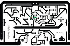
Okay, here is v1.1 of the PCB with the routing fault fixed. This does not yet fix the instability concern. Carlos will decide the necessary circuit mods for that first, then I'll modify the PCB again if needed.
..Todd
..Todd
Attachments
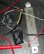
Fine dear Taj, i have worked all nigth long, and the amplifier is now ready to go!
Your board was tested twice, i have built two amplifiers in the most strange and crazy way possible, and now it is rock stable.
Here is the modifications that made it stable, only two capacitors and finished!
Happy new year folks, was not Christmas gift, but for the next year, listen the BEST WIDE WORLD EVER MADE AUDIO AMPLIFIER.
regards,
Carlos
Attachments

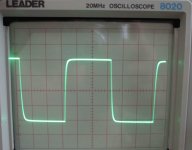
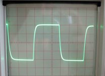
Here you have 10 Khz and 20 Khz square wave pictures
I am already preparing the text/audio explaining how the amplifier works.
This next year, build the best amplifier we can have, thanks to Doctor Douglas Self and my hard work too.
You welcome folks!
here you have the sweep, youtube video:
YouTube - Dx Blame ES, sweep from 4 to 30 Khz
ahahahahah!
I am already preparing the text/audio explaining how the amplifier works.
This next year, build the best amplifier we can have, thanks to Doctor Douglas Self and my hard work too.
You welcome folks!
here you have the sweep, youtube video:
YouTube - Dx Blame ES, sweep from 4 to 30 Khz
ahahahahah!
Attachments
I am not kidding, wanna the best?
Build the Dx Blame ES
This is the best!
regards,
Carlos
Build the Dx Blame ES
This is the best!
regards,
Carlos
An externally hosted image should be here but it was not working when we last tested it.
Man!..you will try to kiss uncle Charlie so happy you will be
Also have to kiss Doctor Self too.
ahahahahah!
You gonna dance, do not waste your time building other amplifiers.... all mine is now junk compared to this one.
YES!, the TAJ board is almost ready, a track to cut, a wire to solder as jumper, read the thread with calm, the last two pages, you have the schematic i have posted, the last one with two capacitors in red.
Doing those things, soldering these capacitor under the board, then you gonna visit heaven, and will be there till the last of your days, listen Paradisiac music from an awsome amplifier, a gift from Douglas Self and my gift too, i have worked hard to make it even better than the original.
Many multiple congratulations to uncle Charlie, yeah!, i deserve that!
Thank you by the congratulations
ahahahahahah!
regards,
Carlos
Here is an audio sample, the youtube video has not all that
audio quality, because has passed three encoding process, first to produce the microphone recording and to register with 128K or sample, MP3, and 44.1 during the generation.
Second entered to Photo2Video freeware software to join the picture with the audio, there the audio is almost destroyed, them the AVI to Flash transcodification made by the Youtube.
If you want better audio, write to me informing your Email adress, not the forum internal mail system, and they i will upload you the MP2, 128K master, the first recording without those next 2 encodings.
It is 1.43 Megabytes size....quality is much better.
For a while, listen the multiple encodings result:
YouTube - The best world audio amplifier
regards,
Carlos
Yes Carlos I will build it.Is Taj his PCB layout ready to etch?
Hi meanman1964,
I think you should wait a couple more days for a new PCB layout that includes the 2 new capacitors.
..Todd
- Status
- This old topic is closed. If you want to reopen this topic, contact a moderator using the "Report Post" button.
- Home
- Amplifiers
- Solid State
- Dx Blame ES .... based into the Blameless, i am trying a new amplifier