This is what drive me mad with the Dx Blame ES
YouTube - Off set overflow
You can increase bass reducing the power transistor emitter resistances to 0.1 ohms, or even to supress them!
If you want the amplifier for treble, then reduce the input capacitor to 1uf and increase the output power emitter resistances to 0.47 ohms or even 1 ohm (to 8 ohms speaker, do not use 1 ohms or 0.47 ohms with 4 ohms speakers!)
regards
Carlos
Attachments
Last edited:
There's no power on thump in the Dx Blame ES
Listen Rudi Ratlos and forum friends,
The sound is so real that i hold the telephone to answer the incoming call!..was the sound from the youtube video!
YouTube - Observe Rudi
Carlos
Listen Rudi Ratlos and forum friends,
The sound is so real that i hold the telephone to answer the incoming call!..was the sound from the youtube video!
YouTube - Observe Rudi
Carlos
the power transistor emitter resistances to 0.1 ohms, or even to supress them!
regards
Carlos
Very interesting idea, Carlos
")
I 'supressed' these resistors about 7 years ago during development of a class A amplifier, the only result was a pile of buried 2SA1302/2SC3281.
Last edited:
Hi,
If memory serves, I believe that there was a AES article in 1983 by Terje Sandstrøm of Electrocompaniet that describes influence of emitter resistors on distortion, in A/B output stages. I haven't read the paper and don't know if the results are valid, but the a local magazine designed an output stage, without emitter resistors, and claimed reduction in distortion. Perhaps Pavel could run it through his simulator?
mkc
It is not needed. Actually with 0R1 you get better linearity and less crossover distortion than with 0R22. BUT, there is a game of reliability and thermal stability as well. With Re = 0.00 ohm, you get nothing but second breakdown by thermal runaway (if you do not work with a closed device) and destroyed output devices.
You should observe what is going on in our forum in the place to watch only your own
schematics,
There are hundreds Dx amplifier without these resistances, working for several years long.
Prejudice folks, you should recicle or put some oil in your minds.
These resistances are needed to equalize when you use more than one pair, if you have a single matched output pair they are not needed.
The years my amplifiers are working fine, built by several forum friends proves you are wrong!
Also output coils are not needed, i was using to remove overshot from the square wave, now removed i can even remove them too.
John Curl told output coils are not needed also.
You guys are filled with theories, what about to try those things, assemble an amplifier and install and remove emitter resistances...do it and see what happens.
Will not produce any test for you, do by yourselves, you behave arrogant while need to learn things into the real world, doing, not watching simulators or reading texts.
Will not discuss with you anymore, you do not build Dx amplifiers, so, do not belong to the crew.
regards,
Carlos
Last edited:
My people is constituted, in the big majority, by hard workers. Gladly. Carlos
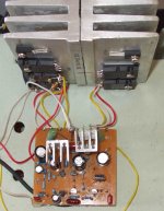
Hmm... that circuit board was not etched using my artwork, but it obviously used it for a template. No problem there, but it will not be a conclusive test to determine if my PCB design works properly. I would like to see someone etch the exact pattern I submitted, to be sure.
...todd
With a single pair of output devices, the emitter resistors reduce transconductance (does someone understand this word?) to help matching the Vbe temperature coefficient of the output devices to that of the Vbe multiplier.
Usually Vbe multipliers run a bit short of dVbe/dt (t=temperature, not time), I used to solve that with a composite Vbe multiplier where the reference transistor was a high current TO-92 operated at a very low bias to get higher dVbe/dt and match TIP35C/TIP36C with only 0.1ohm emitter resistors, which is not easy as they are quite prone to thermal runaway (high dVbe/dt).
Higher voltage lower current japanese transistors seemed to have more emitter resistance "built in" resulting in lower transconductance and easier bias stability.
I don't remember seeing Carlos using adjustable bias on his previous projects, as it brings some new potential problems to solve. How much bias is being used in this amplifier when the emitter resistors are out of the circuit? Is the resistance of the wires that connect output deivces to main pcb being considered?
Last edited:
You see friends, they are with us, in this same forum for years long
And use to criticise things other does!
They do not even see what is in front of their faces!
The Dx amplifier was posted and assembled by more than 100 persons around the world, no one complained about fire or damage because of these emitter resistances... and those critics, they have never observed the amplifier HAS NOT the output emitter resistances.
Return to your own threads boys, and take care of your "Few Amps" ....those ones only few guys assemble.
Do not waste your time discussing folks, already in the ignore list, i feel a disrespectfull behavior from you, not a friendly intentions in your words, not a cooperative thing, trying to reduce my importance and remove the value of my amplifier...this is annoying and i will not accept anyway.
Will not read your messages since i perceive they're not friendly, or cooperative, with good feeling inside your hearts.
Carlos
Attachments

Last edited:
They use to talk dear Taj, they want you to listen them
they want to give you advice (conselhos), they want to fix your possible mistakes, they want to be your Consultant when you have not asked that.
But they do not listen you, they do not even build your amplifiers to evaluate, they go criticising even without observe things in details, while you talk or write they go thinking about their own beliefs and ideas without concentrate , they do not want even to know your ideas...you know.... deaf! and go speaking only.... they want YOU to listen them, to follow their ideas.
They want attention, but without give you attention....one way relationship...they say...you listen..you follow... this way.
It is enougth, those folks will receive what they deserve.
Imagine that Todd?..... all those years, in the same forum, and they have never really watched, with attention, the Dx amplifier schematic... from time to time, as nobody assemble their amplifiers (very few folks does) when have nothing to do, then they came to visit others in an air raid to trow bombs.
You see...one way conversation, they talk to you, you listen... and talking absurds... no amplifier was burned because the lack of emitter resistances!
I like to talk too, and of course i appreciate folks that listen me..these ones do not listen...so.......
Family dear Todd, maybe difunctional as you told, but here, we do not trow bombs in our family members, we support them unconditionally, we do not use sarcasm with our family members, nor ironies and we never try to diminish the importance of them laughing about them, or producing jokes to make our family members look ridiculous or idiotic.... I think, the same in Canadá, as i know you are someone has good feelings in your heart and has class, of course, came from a decent family and you will support them for your whole life, even doing sacrifices for that... because you are man!
regards,
Carlos
Last edited:
BD139/140 transistors, they are good, they can work at 100 Megahertz, i have built several transmitters using this one, Radio Frequency transmitters operating 108 Megahertz, also i have used as drivers (with some losses) in 144 Megahertz Radio Amateurs VHF transceivers, also in CB Radio Transceivers ad 10 meters SSB transceivers... do not tell me they are not good.... i will turn mad imediatelly, i am sure they are very good for audio.
Carlos,
I can tell you the BD135-140 are good, I have done similar things as you with these wonderful transistors, for already around 25 years ago I built a FM transmitter working around 100-108 MHz on a BD137 if my memory serves me, the BD137 itself was both the output transistor and the FM modulator. But these "pirate transmitters" as we called them are illegal...
Cheers Michael
Yep, those consultants are filled with beliefs and prejudices
some of them are living books, that walks and talks but in the essence they are not more than living books, and the bad ones, filled with prejudices too.
BD139 are lovely, so good they are used these last 50 years, now a days there are amplifiers using them, they go lovely installed as drivers in the Dx amplifiers.
I was watching, after short the emitter resistance and have much more bass!, the distortion in the simulator even reduced!.
You see, and they go defending the emitter resistances. they have not tried with and without for sure, the difference is a hell clear.
See the images, the small number is THD without emitter resistances...and i did not tell the simulator software (it has no ears to listen me) that i was using inductive...ahahahahahaha!
So, if inductive, the result would be even worse, emitter resistances when inductive, use to sound in a very clear way.
Doctor Jan Dupont once said, not to show himself, a real intention to cooperate with my progress..he said..".even small resistances in series with the output line will ruine the damping and the bass will be worse!"
So, thinking about...emitter resistances are in series with the two amplifier halves output...resistances in series with the output you can apply here, have only to shake the head and oil the brain to see that.
That sonic signature, the trebly character you have into the Blameless and copies will be reduced when you reduce or even remove emitter resistances.
Do that only if you will be operating using 35 volts supplies and a single pair of transistors..never operate without emitter resistances when you are using more than one pair...they are there to help us a lot equalizing the several transistors power dissipation.... even if they have different gain.
Observe that...if you have one transistor with gain 150 and other with gain 50...what gonna happens without the emitter resistance?.. the one has more gain will drain more current and will take to itself the biggest ammount of current, when the other will work cooler.... this way the one works more will be hotter and may burn.... using current equalizing resistances (these ones you use at the power transistor emitters) the one having more current will produce a bigger voltage drop over the emitter resistance... the more the current the bigger the voltage drop, this way, voltage from colector to emitter will be reduced... when you calculate the power in those two transistor, the gain 150 and the one with gain 50, then multiplying VCE volts by IC amperes then you will have almost the same power to both transistors IF they will have their emitter resistances.... local feedback, and other nice names are all bull, well, all secondary advantages.
regards,
Carlos
Attachments


Last edited:
Carlos,
I am very surprised by your reaction an by size of Your ego, sorry..I posted only warning , posted schematic should simply not be dangerous. I posted several times to this thread, and I see some changes in "Your" amplifier (moved Boucherot cell remving capacitors from wrong places, fuse in output..) , according my posts. Try to buy Self´s book and read it, You wil find many answers..
But do what You want, it is Your reputation and name,but some of Your theories are very funny. And simulations are not measurements, real world is quite different.BTW. theories, I made several thousand of PA amplifiers , they are working at very hard conditions (clubs, musicians), some pieces 10-15 years, and many(several hundreds) HiFi amplifiers , too. It is my only job last 20 years.
Measured performance of my amplifier is attached, try to post Yours
Attachments
![THD100W[1].png](/community/data/attachments/154/154302-72d50ae7760ab70c573eaa65f426d2bc.jpg)
Last edited:
Build Dx amplifier folks, and feel the glorious moment of real happyness in your life
Dx Corporation always welcome builders... also will help and support them.
Theorists, Consultants, Advisers are not welcome... they are not productive, they are counter productive, produce nothing, just bad moments.
The thread is to share amplifiers for old Dx builders, the sex of anjos, electrons colour, his dressings and the direction the electrons goes spinning are not my personal interest.
I am searching for folks to share my tested amplifiers, there's no other interest... this one is needing folks to test Taj boards.
Theorists can open their own thread and expose their ideas.
regards,
Carlos
- Status
- This old topic is closed. If you want to reopen this topic, contact a moderator using the "Report Post" button.
- Home
- Amplifiers
- Solid State
- Dx Blame ES .... based into the Blameless, i am trying a new amplifier