I like to upsample to integer multiples, so I upsample 44.1kHz material to 176.4kHz and 352.8kHz. Many people consider this as oversampling because of the integer multiples.
I can't honestly say that I notice much difference between 176.4 and 352.8kHz. 176.4kHz already sounds very nice in my system. Music is reproduced with a good amount of realism, and I can listen all day without fatigue. If I were to listen blind, I probably would not be able to tell the difference between 176.4 and 352.8kHz.
For me, being able to play music at 352.8kHz is more validation of my diy copper foil/veroboard TDA1541a dac board than anything else. Also like most diyers, it's always trying for more to see if I can get that last little bit. That is why I think my next move is to try I2S direct, bypassing USB to I2S, even though I am very happy with the sound as is.
A bit off-topic but one recent tweak that I did made a noticeable difference in sound. I have all of my digital boards and power supplies mounted on a piece of MDF board (see previous posts), and there was some transformer hum.
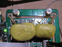
Even though I have the clock board suspended with latex O-rings cut from surgical rubber tubing, I figured that the XOs on the clock board and on the WaveIO were being affected by the transformer vibration and hum. So I placed some adhesive putty (similar to Blu Tack) under all of the five transformers that are on the board to provide vibration isolation. That got rid of the transformer hum, and the sound, which was very open already, opened up some more.
A cheap but very satisfying tweak for me.
I got inspired to isolate the transformers when I saw on another forum where a tweak to isolate a toroidal transformer in a digital device using donut shaped corrugated cardboard under the transformer was offered commercially. It was supposed to make a dramatic difference in sound.
I'm decoupling the digital front end with corks as it is a device I have often on the table ! I took also with the clock board II the rubber donnuts !
As I am finishing the casing of my DAC, I'm going to screw the traffos on thin cork paddles, but I believe there are no better vibration trap than rubber or blue-tack (plastiscine) !
As I am finishing the casing of my DAC, I'm going to screw the traffos on thin cork paddles, but I believe there are no better vibration trap than rubber or blue-tack (plastiscine) !
A bit off-topic but one recent tweak that I did made a noticeable difference in sound. I have all of my digital boards and power supplies mounted on a piece of MDF board (see previous posts), and there was some transformer hum.
Even though I have the clock board suspended with latex O-rings cut from surgical rubber tubing, I figured that the XOs on the clock board and on the WaveIO were being affected by the transformer vibration and hum. So I placed some adhesive putty (similar to Blu Tack) under all of the five transformers that are on the board to provide vibration isolation. That got rid of the transformer hum, and the sound, which was very open already, opened up some more.
A cheap but very satisfying tweak for me.
I got inspired to isolate the transformers when I saw on another forum where a tweak to isolate a toroidal transformer in a digital device using donut shaped corrugated cardboard under the transformer was offered commercially. It was supposed to make a dramatic difference in sound.
Very smart idea. Can I have your updated pictures? I'm interested in the "surgical rubber tubing". I gave up rubber ring suspension solution because I can not find suitable ones.
Also I'm wondering what is the "donut shaped corrugated cardboard" they used
") .
.Regards,
Ian
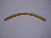
The surgical rubber (latex) tubing that I used is 3/8" diameter and I bought it at my local Home Hardware. I think Home Depot and other hardware stores also sell it. When I was a kid many, many years ago, we used to buy it for our diy slingshots.
You can vary the strength of the diy bands or O-rings by varying their width.
The corrugated cardboard toroidal tweak is here:
Gustard X20 Mods
It must be "special" cardboard.
Here is where I first read about it:
http://www.head-fi.org/t/780385/gustard-x20-dac/615
I have no interest in that dac btw (tda1541a rules).
Attachments
Last edited:
The surgical rubber (latex) tubing that I used is 3/8" diameter and I bought it at my local Home Hardware. I think Home Depot and other hardware stores also sell it. When I was a kid many, many years ago, we used to buy it for our diy slingshots.
You can vary the strength of the diy bands or O-rings by varying their width.
The corrugated cardboard toroidal tweak is here:
Gustard X20 Mods
It must be "special" cardboard.
Here is where I first read about it:
Gustard X20 DAC - Page 42
I have no interest in that dac btw (tda1541a rules).
Thanks Ben, look wonderful
Any thing medical grade would be the best. It makes sense.
BTW, what are the two piece yellow material for the clock board?
Regards,
Ian
Last edited:
That is why I think my next move is to try I2S direct, bypassing USB to I2S, even though I am very happy with the sound as is.
Do it! It makes a huge difference, a real game changer.
BTW, what are the two piece yellow material for the clock board?
The yellow blobs on the XOs are more of the yellow tack for further damping and vibration control. I have also placed them on the XOs on the WaveIO.
I had read somewhere on diyAudio (maybe on the FIFO thread) about it.
Do it! It makes a huge difference, a real game changer.
I am thinking of purchasing an Odroid C2. I hope it has enough power to do SOX 8x oversampling on the fly. I would pair it with Ian's recently announced I2S isolation board for Pi/Odroid.
I just found where I read about damping the XOs:The yellow blobs on the XOs are more of the yellow tack for further damping and vibration control. I have also placed them on the XOs on the WaveIO.
I had read somewhere on diyAudio (maybe on the FIFO thread) about it.
http://www.diyaudio.com/forums/digi...based-asynchronous-usb-i2s-interface-233.html
I am thinking of purchasing an Odroid C2. I hope it has enough power to do SOX 8x oversampling on the fly. I would pair it with Ian's recently announced I2S isolation board for Pi/Odroid.
Yes,enough power
"I've seen it go up to around 14% when upsampling from 44 --> 384kHz using this SoX setting".
Archimago's Musings: SET-UP: Low Power Linux Audio Player (ODROID-C2 & Volumio 2)
"192 --> 384kHz upsampling using "soxr very high" setting which is the most processor-intensive option:
As you can see, mpd is using up ~12% processor load. I've seen it go up to around 14% when upsampling from 44 --> 384kHz using this SoX setting."
Doesn't seem right - only 2% increase.
Using a Debian HP Chromebox with an Intel 2955U processor and upsampling with SOX via pipe in MPD, I get about 11% cpu usage for 44.1 to 176.4kHz and about 20% cpu usage for 44.1 to 352.8kHz.
Do it! It makes a huge difference, a real game changer.
With [FIFO > ISO > Dual XO] following either [USB to I2S] or [(direct) I2S] input, how can this be explained??
LH/S
Last edited:
Sorry i dont know what you mean, please expandWith [FIFO > ISO > Dual XO] following either [USB to I2S] or [(direct) I2S] input, how can this be explained??
LH/S
Hi Supra, I believe what LH/S asks is how an USB source or a direct I2S one can make a diference if all is isolated and reclocked after by the complete Ian front-end set !
For the others and clarification, I highlight you have now a Raspberry Pi 2 with the IanCanda I2S adaptator on the 40 pins header if I remember which is feeding the FIFO, then the isolator, then the Clock board (XO soldered or adaptator?), then PCM board with AYA 2014 or without PCM board and an other DAC (If I'm always correct?)!
But despite the I2S you also testimonied you heared a difference when feeding the Raspebbry with a LDO or an external LIPO cell ?!
Which is push me to ask : damned, what is your speaker ? And which is also an indirect answer to LH/S than despite the FIFO and isolator, the source still seems to made a difference, surely a less fewer one than without FIFO.... Supra should be in the last refinments about his setups... perhaps ?!
For the others and clarification, I highlight you have now a Raspberry Pi 2 with the IanCanda I2S adaptator on the 40 pins header if I remember which is feeding the FIFO, then the isolator, then the Clock board (XO soldered or adaptator?), then PCM board with AYA 2014 or without PCM board and an other DAC (If I'm always correct?)!
But despite the I2S you also testimonied you heared a difference when feeding the Raspebbry with a LDO or an external LIPO cell ?!
Which is push me to ask
: damned, what is your speaker ? And which is also an indirect answer to LH/S than despite the FIFO and isolator, the source still seems to made a difference, surely a less fewer one than without FIFO.... Supra should be in the last refinments about his setups... perhaps ?!
Last edited:
"I highlight you have now a Raspberry Pi 2 with the IanCanda I2S adaptator on the 40 pins header if I remember which is feeding the FIFO, then the isolator, then the Clock board (XO soldered or adaptator?), then PCM board with AYA 2014"
yes that's right. I dont know why no-usb is better, but its clearly audible. A digital engineer told me that usb sends packets backwards and forwards, and the no usb is a constant stream and that is what it sounds like- coherent .
I have various speakers , horns, stats and direct radiators, but my "best" speaker is my 30 year old Acoustat 2+2's , 8 foot line source, with modified interfaces and bi-amped with 2 1000W capable stereo amps. A tube DHT preamp of course.
............I just found my old TDA1541 chip (no A), I'll try the maximal Fs working with PCM board to see what's the physical limitation of 1541 once I get time!..............
Ian
Using your PCB I am running a couple of 1541's (No 'A') and they're good up to 384kHz!! They don't seem to like 705.6kHz or 768kHz but then neither do the A versions.
I quite like the sound of the 'non-A'. Will listen for a while before going back.
Thanks again for your PCB Ian, it's nice to be able to run the TDA1541 up to those Frequencies to see just what its capable of.
Best regards,
P.
Hi percival007,
That's a great news! It's unbelievable that TDA1541 (without A) can run at 384Khz. Thank you for your update.
Hopefully I can confirm it on my 1541 DAC fixture. I'll let you know.
Regards,
Ian
Sorry i dont know what you mean, please expand
Hi, just as Eldam suggests - my thinking is that if all is completely isolated then how the difference once the signal is I2S. Data packet irregularity perhaps with USB - ok, but after it is converted to I2S - it is FIFO buffered, isolated and then reclocked.
IIRC proof of concept from Ian for the FIFO was that his Krell transport was indistinguishable from a cheap transport (could have been a generic dvd player, I dont recall the details) but you'd get the idea, however, and IIRC this was all SPDIF to I2S..
It makes me wonder if the 'bit perfect' ripped CD can be sent via USB as 'bit perfect', and also can the USB to I2S conversion be 'bit perfect'?
Ian ??
LH/S
Last edited:
- Home
- Source & Line
- Digital Line Level
- Drive NOS AD1865/62,PCM1704/02/63,TDA1541 from FIFO: Universal I2S-PCM driver board