Hi, just as Eldam suggests - my thinking is that if all is completely isolated then how the difference once the signal is I2S. Data packet irregularity perhaps with USB - ok, but after it is converted to I2S - it is FIFO buffered, isolated and then reclocked.
IIRC proof of concept from Ian for the FIFO was that his Krell transport was indistinguishable from a cheap transport (could have been a generic dvd player, I dont recall the details) but you'd get the idea, however, and IIRC this was all SPDIF to I2S..
It makes me wonder if the 'bit perfect' ripped CD can be sent via USB as 'bit perfect', and also can the USB to I2S conversion be 'bit perfect'?
Ian ??
LH/S
I cant answer your questions, im not a digital engineer, but I own Amanero, JLSounds and exa usb-i2s convertors and none of them come close to the raspberry direct i2s .
Purely subjective of course, but there's no going back for me.
Sorry, should have asked before... Supra, what software are you using for music playback with the USB front end?
LH/S
Oh ive tried just about everything windows or mac based, with the raspberry im using moode in linux.
Yeah me too, the Odroid looks interesting.
BTW yesterday I tried Moodes resampling feature with everything upsampled to 192KHz, to my 1541.
Usually I dont think there's much benefit to this, but this one does actually sound quite different. Not sure yet if its "better" but I like it, and it certainly makes a difference.
BTW yesterday I tried Moodes resampling feature with everything upsampled to 192KHz, to my 1541.
Usually I dont think there's much benefit to this, but this one does actually sound quite different. Not sure yet if its "better" but I like it, and it certainly makes a difference.
Happy He did it, I asked this item to him in a wisch list, like also the far more complex possibility to add a BruteFIR correction too...(but was too complicate as an external development he said).
Moode seems to be one of the best distro with the Arch Linux ones with the Squeeze Box media center core... Volumio worls also on the Odroid c1 +, but not the brand new Odroid (64 bits)
I believe the Layout of the Raspberry II can be a problem above 192 K Hz despite the I2S plug due to its layout... If I remember Ian measured that... don't remember really !
I also made a lot of experiment with and without the PCM board... Both have different qualities with my speaker/room/AYA Dac...
Numeric stuffs have not finish to surprise me")
Moode seems to be one of the best distro with the Arch Linux ones with the Squeeze Box media center core... Volumio worls also on the Odroid c1 +, but not the brand new Odroid (64 bits)
I believe the Layout of the Raspberry II can be a problem above 192 K Hz despite the I2S plug due to its layout... If I remember Ian measured that... don't remember really !
I also made a lot of experiment with and without the PCM board... Both have different qualities with my speaker/room/AYA Dac...
Numeric stuffs have not finish to surprise me
Last edited:
Oh ive tried just about everything windows or mac based, with the raspberry im using moode in linux.
Thanks mate.
Ian - any idea as to the limitations of USB to I2S for purpose with your devices?
Regards,
LH/S
Last edited:
I cant answer your questions, im not a digital engineer, but I own Amanero, JLSounds and exa usb-i2s convertors and none of them come close to the raspberry direct i2s .
Purely subjective of course, but there's no going back for me.
Direct PCM (that is, we could call it the synchronous I2S mode) should be just as simple in the software.
Hi guys!
Ian - are there any FIFO and I2S-PCM boards left available?
If yes, could you pm me the price for one of each (I need only 44,1kHz for TDA1541A, shipping to Slovenia), please?
Best Regards,
Saso
Hi Saso,
I still have some FIFO KIT but no any I2S-PCM board left. I might consider running a new production.
Please let me know if there is anything I can help.
Regards,
Ian
Hi Ian,
thought I'd update you on my progress with your board in my DAC.
I have got it all mounted on the chassis of the case today and am listening to everything up-sampled to 352.8 or 384, whichever means 'less maths' for my PC !
Very nice indeed. Thanks again for your Board, it just helps so much to get the best from the 1541.
P.
Attachments
Hi Ian,
Have a question about the supply input pins of the Clock II board and the PCM one please :
If not using the main input board but our own reg with the VIN,GND, 3.3 V input pins :
what is bypassed on your boards ?
- the main polymer cap ?
- the internal reg as well ?
- what is the left caps ? XR7 smd ?
I'm using LiPoFe4 with J5 main input on the Clock II now with Vin and 3.3V pins shorted...
Can I have a better result by using the cell on the 3.3V and gnd pin (so no external reg) : will the cell see the internal reg or directly the last X7R decoupling caps on the board ?
Or should I use instead this 3 pins with an external low noise clock (TS7A for instance) but feeded by the A123 cell (with a promatted output at 3.2 V or less to allow the regulator LDO to do the job... the cell is outputting 3.27 !)
thanks in advance,
regards
Eldam
PS : I use it with the FIFO + isolator !
Hello,
I would need some help. I did tried to read back some, but I could not read all, I hope it is not something was on topic times before.
So, my problem is the following :
From a RPI I feed an Amanero combo 384, from that the I2S to PCM board. I use U.FL cables between the interface and the AD1865 board.
It works fine with 16 and 24bit files, 44, 48, 88, 96kHz sample rate. It does not work with 192kHz sample rate. The audio is loud and fully distorted what comes out of the chip. I was investigating why. I think the AD1865 must handle it, since that is designed for 8-16 times oversampling of 44/48kHz. That is plenty. In fact, according to the datasheet it should not work in NOS config, the minimum clock what the datasheet calls is 13.5MHz, while with 44kHz * 32 or 64 is still a lot less than that.
I do use AD1865 in another DAC, with SPDIF receiver, but there the SPDIF receiver is the limitation.
I was thinking is the master clock from the USB interface is not enough, but the minimum requirement is 128*192kHz is 24.576MHz and this is what the amanero outputs.
Do you guys have idea what could be wrong?
Thanks,
JG
I forgot to note an important thing:
I'm not sure the termination of the signals are right. From the USB interface to the I2StoPCM board, I can not measure termination resistor on the I2StoPCM board, which I'm not sure it is right, but I guess it is since Ian know what he is doing. However, I can see significant ringing on the singnals.
Also, on the input of the AD1865 board, I have place for the termination resistors, but I did not placed them, I do not know what value should it be. There is even more ringing on those lines. I think it is not the root cause of the problem above, but anyway, it should be corrected. What termination resistors should I use? 47 ohm?
Should I place some termination in the input of the I2StoPCM board?
Thanks a lot,
JG
I forgot to note an important thing:
I'm not sure the termination of the signals are right. From the USB interface to the I2StoPCM board, I can not measure termination resistor on the I2StoPCM board, which I'm not sure it is right, but I guess it is since Ian know what he is doing. However, I can see significant ringing on the singnals.
Also, on the input of the AD1865 board, I have place for the termination resistors, but I did not placed them, I do not know what value should it be. There is even more ringing on those lines. I think it is not the root cause of the problem above, but anyway, it should be corrected. What termination resistors should I use? 47 ohm?
Should I place some termination in the input of the I2StoPCM board?
Thanks a lot,
JG
Hi Giordano,
The source termination resistor has to be placed right after output. So, if you saw ring on the input of PCM board, you should place those termination resistors right after signal drivers of the source (I guess your USB), normally 33 ohm to match 50 ohm transmission line(u.fl cable). You can not place them at inputs of PCM board.
No any termination needed on your DAC. PCM board already has those termination resistors on all signals.
Another thing I have to mention is that you need to make sure your oscilloscope has enough bandwidth the see a 1ns raising edge. Otherwise, what you saw might be incorrect. PCM board use GHz devices.
Good luck to your project!
Regards,
Ian
Hi Ian, thanks for your reply!
I can not measure resistance on the output either. I mean, can not measure resistance on the I2StoPCM board output. I do something wrong or it is right this way?
On the other hand, I see no termination resistors on other DAC designs either. I do not know it is right or not. Just try to find why my DAC does not work on 192kHz.
Thanks,
JG
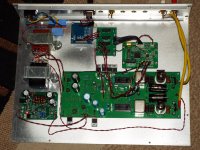
This is my current setup:
http://kepfeltoltes.hu/161005/DSC_0044_www.kepfeltoltes.hu_.jpg
I also have a FIFO board with OSC, but that is in another circuit. If this turns to be the better (and it should) than I will move that too.
JG
An externally hosted image should be here but it was not working when we last tested it.
http://kepfeltoltes.hu/161005/DSC_0044_www.kepfeltoltes.hu_.jpg
I also have a FIFO board with OSC, but that is in another circuit. If this turns to be the better (and it should) than I will move that too.
JG
- Home
- Source & Line
- Digital Line Level
- Drive NOS AD1865/62,PCM1704/02/63,TDA1541 from FIFO: Universal I2S-PCM driver board