Morays design
Hello Moray:
Very cool design:
I think I have it figured out. You appear to have taken the principals of the Karlson and the MLTL and come up with an interesting hybrid. Excellent idea, very innovative combination.
Thoughts:
The back wave could be tuned and a port included to vent into front portion.
Another option may be to make the back portion of the enclosure into a TQW line. The challenge will be to get the driver as close to the middle of the line as possible.
It looks like this discussion needs a home of it's own.
Good for you
design basics
SCD: the back wave line is a 1/4 wave TL and the terminus of that line does infact terminate into the front Karlson coupler. This is about as close to a free lunch as it gets. The increased load to the driver and improved impedance match to the air in the room are proved by the fact that a driver in this design has greater impact and output as compared to the same driver in either a ML TL or a reflex box. Even at high level output the driver motion is very well controlled far better than in any other design that I have ever tried. All the best for now. Regards Moray Jamesl
SCD: the back wave line is a 1/4 wave TL and the terminus of that line does infact terminate into the front Karlson coupler. This is about as close to a free lunch as it gets. The increased load to the driver and improved impedance match to the air in the room are proved by the fact that a driver in this design has greater impact and output as compared to the same driver in either a ML TL or a reflex box. Even at high level output the driver motion is very well controlled far better than in any other design that I have ever tried. All the best for now. Regards Moray Jamesl
Further design data
Here is the content of a post from earlier today at the fullrange driver forum. I hope this spawns some investigation here. Karlsons and thier varients have a very poor response from those who have never tried them. I think perhaps that it is thier strange look combined with the fact that few appreciate just how the Karlson coupler radiates. Most seem to think that there will be huge difraction problems. This in fact is not the case. The tapers on a Karlson coupler act as a broad band resonator acting over a wide range of frequincies unlike the verynarrow band of resonant augmentation provided by a resonant reflex vent or port. The Karlson coupler augments output more in fashion to that seen in a horn design. These qualities are most welcome when using a fullrange low xmax style driver.
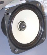
The cabinet shown is an early version designed for a fe127e Fostex driver but would also suit an RS 1197 or similar driver. The back line is equal to the driver Sd (cross section) and is approximately a 1/4 wave TL. The driver baffel is only as large as necessary and the line terminus again equals driver Sd. The height of the ellyptical reflector is equal to the driver baffel height (vertical above the terminus opening). You will have to play with different taper curvatures to see what works best. Damping is also critical to make this design work well. Only damp the line not the coupler. I have found that felt damping (1/4 inch) works very well and keeps the lines fundamental resonance strong while damping upper frequincies inside of the line well. Overall damping of the lines Q can be achiever with dense fiberglass or open cell sponge foam at the terminus of the line. A higher aspect cabinet is better for bass than a squat design but I think that at least an inch on either side of the driver is a good idea so that about sets the parameters of the design for you. Somebody have at it and get back to me with any results or clever ideas. All the best Moray James.
Here is the content of a post from earlier today at the fullrange driver forum. I hope this spawns some investigation here. Karlsons and thier varients have a very poor response from those who have never tried them. I think perhaps that it is thier strange look combined with the fact that few appreciate just how the Karlson coupler radiates. Most seem to think that there will be huge difraction problems. This in fact is not the case. The tapers on a Karlson coupler act as a broad band resonator acting over a wide range of frequincies unlike the verynarrow band of resonant augmentation provided by a resonant reflex vent or port. The Karlson coupler augments output more in fashion to that seen in a horn design. These qualities are most welcome when using a fullrange low xmax style driver.
The cabinet shown is an early version designed for a fe127e Fostex driver but would also suit an RS 1197 or similar driver. The back line is equal to the driver Sd (cross section) and is approximately a 1/4 wave TL. The driver baffel is only as large as necessary and the line terminus again equals driver Sd. The height of the ellyptical reflector is equal to the driver baffel height (vertical above the terminus opening). You will have to play with different taper curvatures to see what works best. Damping is also critical to make this design work well. Only damp the line not the coupler. I have found that felt damping (1/4 inch) works very well and keeps the lines fundamental resonance strong while damping upper frequincies inside of the line well. Overall damping of the lines Q can be achiever with dense fiberglass or open cell sponge foam at the terminus of the line. A higher aspect cabinet is better for bass than a squat design but I think that at least an inch on either side of the driver is a good idea so that about sets the parameters of the design for you. Somebody have at it and get back to me with any results or clever ideas. All the best Moray James.
...I get the impression then (needs further study obviously) that this K-coupling still needs a long line in the back for deep bass, which would dictate a high aspect cabinet indeed for a small diameter driver.
But the photos of these boxes that I have seen look like they have *short* lines...
What gives?
But the photos of these boxes that I have seen look like they have *short* lines...
What gives?
K-Line
Stocker: the line is approximately a 1/4 wave line, so it's length will be determined by the driver (parameters) of choice. Lower Fs longer line. No free lunch there unfortunately. Longer lines (than required) will not produce deeper or lower bass in fact a longer line will reduce bass output and make the cabinet larger and more difficult to build than is necessary.
The photo shown, was as mentioned, an early prototype. The driver had an Fs of about 80 Hz.. No smoke or mirrors here. You get what you design. A driver with a 70-80 Hz Fs yields a very compact enclosure with good efficiency which will mate to a powered sub very well. Why build larger cabinets than necessary to get the job done especially in a HT system where size is almost always an issue? I think that the Fostex ff85k would probably make an excellent monitor when combined with a mono or stereo sub set up. The small cabinet size insures excellent cabinet rigidity from standard materials. A high aspect K-Line sub would make a great stand for such a small monitor.
Thanks for the response and the questions. I hope that these answers help to clairify things. All the best regards Moray James.
Interesting thread that uses the drivers we are discussing:
http://www.diyaudio.com/forums/showthread.php?s=&threadid=45082&perpage=10&pagenumber=1
http://www.diyaudio.com/forums/showthread.php?s=&threadid=45082&perpage=10&pagenumber=1
Re: Moray on the Bow, slightly off topic
There is at most 1 degree of separation from Meitner... i 1st ran into Moray via Bill Perkins
dave
Nanook said:Or a Meitner perhaps?
There is at most 1 degree of separation from Meitner... i 1st ran into Moray via Bill Perkins
dave
Today someone asked if my FE103/40-1197 phase plugs would fit into the FE127.
So i was oblidged to do a dustcapectomy... after a bit of a struggle getting some errant bits of dust cap out of the gap....
The FE127 has quite long voice coil that extends quite a bit beyond the apex of the cone. The 103/1197 phase plug is the right diameter but i think needs about 9-10mm more "shoulder".
It was interesting to see some ripples in the out-of-the-box impedance curve disappeared with the dust cap removal (some came back with the too short phase plug)...
dave
Attachments
phase plug suggestion
Cool Work Dave: could you do a couple of other plugs for comparrison? I was thinking about a short cylinder with a large enough diameter to mostly fill the voice coil former and then mount a sphere on the end about the size of glass marble the kind we used to call "boulders" (smaller than a ping pong ball). Also could you go to your local hardware store and get one of those miniture spot lights with the mini base? They look kind of like a flat door knob. Don't know if you ever saw but Beauhorn use a shape like that in one of thier Lowther horns. Would be cool to see what they do to the plots as well as to the precieved quality of the drivers top end. The fe127e could use a bit more sparkle in the top end. Best regards Moray James.
Cool Work Dave: could you do a couple of other plugs for comparrison? I was thinking about a short cylinder with a large enough diameter to mostly fill the voice coil former and then mount a sphere on the end about the size of glass marble the kind we used to call "boulders" (smaller than a ping pong ball). Also could you go to your local hardware store and get one of those miniture spot lights with the mini base? They look kind of like a flat door knob. Don't know if you ever saw but Beauhorn use a shape like that in one of thier Lowther horns. Would be cool to see what they do to the plots as well as to the precieved quality of the drivers top end. The fe127e could use a bit more sparkle in the top end. Best regards Moray James.
Apologies in advance for not reading all the pages in this thread, but would it be possible for someone to summarize the status? I'm interested in this as a someday project, but after scrolling back many pages I'm not sure where it's at. Has a driver been settled on yet?
I'm thinking about a FR project, particularly after an article in the latest audioXpress using a Fostex FE103. The author at the end mentions another design that I'll have to look into.
PaulB
p.s. Hi Moray, that was you I talked to on the phone a few months back, right? How are things? Bow thawed out yet (don't get down there much)?
Hey Paul: you are close at hand so if you would like you can come over and have a listen to what I have veen doing with the Fostex fe126e as well as the fe166e. I also have a set of fe207e's in a Martin King MLTL cabinet you can listen to. Have not yet got the JLH amp boards installed into the case but soon I hope. Best regards Moray James.
Since Chris sold his FE108ES B-Horns, and is holding off on the FE168ES, we decided that for the interim it would be a good idea to implement the straight bi-pole so he has something to listen too...
we did a few mods to the existing v0.2 to accomodate the particular situation, here is the plan... called v0.3cb.
Changes/implementation details:
1/ aspect ratio is slightly changed to make them narrower & deeper.
2/ sides extended to meet the floor (ie built-in stand)
3/ ported out the bottom
4/ port moved "outside" the box, ends flared slightly, length increased a bit to compensate (and convienently the same as 3 stacked pieces of 3/4" material)
Will be built with BB + MDF for the base & the extra bottom thickness (choosen for its extra mass to lower the centre of gravity)
dave
Attachments
I agree with PaulB, would someone like to suggest a reference driver at least? Maybe a mid-size one that provides a ballance between bass and highs, and is not too expense. Something that would be a good starting point for those of us that have not built a single driver fullrange?
- Home
- Loudspeakers
- Full Range
- diyAudio Full Range Reference Project