MarkMcK said:I am rather skeptical of a 200 hour break in period. Think about it. First, if the driver continues to change over the first 200 hours, what possible reason do we have to believe it will stop changing after 200 hours?
Mark
Hi Mark. The FE127E is my first Fostex driver so I do not know how long break in will take. However, I have read on several occasions that the break in time is in the order of about 200 hours!
Since you have measurements at 20 hours, I think it would be great to get more measurments at 200 hours and compare the two. Since we are all human, I think there is a possibility that after 200 hours, people become acustomed to the sound and say it sounds better.
MarkMcK said:I assume ML stands for mid line.
Mark
The ML stands for Mass Loaded.
Keep up the GREAT work!
Gio.
MarkMcK said:I assume ML stands for mid line
ML stands for mass loading. The restricted terminus does this. Augspurger showed that the mass loading increases the amount of suppresion of higher order resonant modes (ie increased the performance of the low pass function on the output of the terminus)
If it does, then the testing is showing a possible problem with MLs. When fully damped, it is small and therefore probably can be ignored. When fully damped, however, low frequency output is way down. Reducing damping brings up the bass, but also shows much increased magnitude of a spectral repetitive narrow bandwidth dip and then peak. First instance occurs around 400 to 500 Hz.
The position along the line of the driver is used to cancel some of the TLs ripple. It properly positioned it will almost completely kill one of the harmonics -- usually one goes after the 1st undesirable one because it has the largest magnitude. In an ML-TQWT this is most often halfway. On an ML-TL is is usually closer to a 1/3. Tim has choosen 1/2 in this design. For folding it is quite convienient -- especially in a bi-pole.
dave
ML = Mass Loaded, a term coined by Martin King for his work on a restricted terminus quarter-wave pipe. I chose to use Martin's MathCAD worksheets because of it's availability to everyone on this forum and for the accurate modeling it can produce. This also gives everyone here the opportunity to try out the worksheets for themselves using the numbers provided and hopefully offering new and better ideas.
Dave's T-line website, Martin's Quarter-Wave website and G.L. Augspurger's articles for Speaker Builder are excellent places to do some reading on the subject.
My primary goal when using these tools is maximally flat bass response and good phase response while attempting to reduce harmonics in the pipe, in particular the third, first by driver placement then with stuffing.
Secondary goals may include the visual impact of the enclosure and ease of construction.
")
Timn8ter said:Dave's T-line website, Martin's Quarter-Wave website and G.L. Augspurger's articles for Speaker Builder
Don't forget Bob Brine's site http://geocities.com/rbrines1/
The best version (subtly) of Augspurger's paper is the revised one published in the AES journal.
dave
Here is the first of several posts about the test results.
The first set of graphs show the interaction of the enclosure with the driver. That interaction continues up until about 4. 5 kHz. Please do not overreact to the results. All enclosures interact, even open back baffles with wings will interact by backside loading the driver diaphragm.
I suppose one thing to take from these tests is that stuffed or not stuffed, the sound of the loudspeaker will be a combination of the driver and the enclosure. A lot of the interaction goes away with stuffing, but not all.
Good designing and good building,
Mark
Attachments
Today's last post shows the far field, free space response of the loudspeaker comparing vent closed with vent open. The results shown here are repeatable, yet the differences shown are at the low frequency resolution limit of my chamber. While I believe the loss of low frequency output is a function of the loudspeaker and not the test set up, I have little confidence that the amount of difference shown is an accurate reflection of the actual acoustic performance. It may be less or it may be more. The magnitude reduction seen with vent open is likely a notch or dip with the response rising again at even lower frequencies. Few testing labs have the far field low frequency resolution to get the desired detail on this phenomena.
Mark
Mark
Attachments
Without fill, all the enclosures should be showing some ripple... did Tim ever give a specified amount of stuffing (i remember putting ??? in the drawings when i indicated it -- 0.25 to 0.5 lbs/ft^3 is fairly standard)
Unfortunately the linear scale charts make examing the LF results almost impossible and remove any easy way of seeing the periodic pattern any ripples make. Can you repost the results with a log scale?
dave
Unfortunately the linear scale charts make examing the LF results almost impossible and remove any easy way of seeing the periodic pattern any ripples make. Can you repost the results with a log scale?
dave
did Tim ever give a specified amount of stuffing
IIRC, I used .25 lbs per cu. ft. I usually don't go much higher than that.
Dave included a fill spec for the tall and narrow enclosure.
I followed that for the tall and narrow and the round top. Now, while some claim that we hear log, multiples of frequency; quarter wave, half-wave, and so on are linear.
The multiplicity of frequency is much easier to see lin than log.
The enclosure interference is not particularly worse than it is for many other enclosure and driver combinations (and I suggested you not overreact to the ripple seen in the 20 kHz bandwidth testing). Most of it, however, is internal and not baffle step or baffle edge.
You can see that in this last post. This last set of graphs shows the response with the last prefilter design. This design is much more complicated than it looks since it takes advantage of filter interaction and prefilter to driver interaction to do more than the mere sum of its components. This is the best I can do. The better route is a new cone design, but that is best left to Fostex. Ask them for it and maybe they will provide.
I have a tendency to discount anything that does not come up to a fairly high standard of performance. I have to remind myself that this is a driver that costs less than $40 USD. No reason anyone should expect perfection for less than $40.
I am not going to break this driver in anymore. I have already put 26 hours at extremely high drive levels. If you compare the stress of my conditioning period to listening to classical music, it would come out to playing music at maximum driver levels at 10 hours for every one hour of conditioning. I will await those that believe in 200-hour break in periods to show us how the driver changes over that time.
Anyway, with this amount of break in, in the round top enclosure and divided body, I found the best bass sound was achieved stuffing one half of the body with the specified amount of fill and using 1/4 specified amount to loosely filling the half with the port.
Fully filled or filled as described above, the loudspeaker produces more of a suggestion of bass than actual bass. Whether fully filled or filled as described above, the speaker has a slight tubby sound. Often described as the oatmeal tube sound. I have heard worse, but it is audible. The upper mid bass and lower midrange is slightly dense, not open or airy. On complex music, it becomes a wall of sound noticeably lacking in detail and clarity. The upper midrange and treble has a dry edgy sound. I dread using this descriptor since it does use a paper cone, but it is a dry papery sound. This is especially noticeable on sibilance and second and third vocal overtones. High treble remains a little smeared or splashy.
With this prefilter, the response is tamed enough that you can actually hear the sound of the speaker. Since the component sizes are small, the cost of the prefilter is small. Whether you like the sound of it I will leave up to the listener. If you don't there is less lost on the cost of the prefilters than on the Madisound cost of the drivers.
All in all, it is an okay design. Well done people.
Good designing and good building,
Mark
Attachments
MarkMcK said:I followed that for the tall and narrow and the round top. Now, while some claim that we hear log, multiples of frequency; quarter wave, half-wave, and so on are linear.
The multiplicity of frequency is much easier to see lin than log.
????
The ripples should show up on a log graph as relatively equally spaced peaks & suck-outs...
An externally hosted image should be here but it was not working when we last tested it.
On the linear charts to 20k all the info of interest is crammed into the leftmost 5% of the chart.
dave
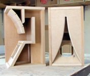
hybrid Karlson/Transmission Line cabinet
just a photo of a cabinet design (one of a series) which shows the general idea of a cabinet in which currently resides a fostex fe126e (has also run with fe127e). I am currently also running a fe166e in a larger version. Excellent results. The chief benefit of this design is that it effectively loads both the front side and the back side of the driver which yields excellent control of driver motion while permitting a good air impedance match between the driver and the air in the room. Size is compact bass response is superiour to a ML TL and dispersion is superb. Hope that this generates some thought. Best regards Moray James.
just a photo of a cabinet design (one of a series) which shows the general idea of a cabinet in which currently resides a fostex fe126e (has also run with fe127e). I am currently also running a fe166e in a larger version. Excellent results. The chief benefit of this design is that it effectively loads both the front side and the back side of the driver which yields excellent control of driver motion while permitting a good air impedance match between the driver and the air in the room. Size is compact bass response is superiour to a ML TL and dispersion is superb. Hope that this generates some thought. Best regards Moray James.
Attachments
Re: hybrid Karlson/Transmission Line cabinet
Very interesting design Moray. Have you done any FR measurements for it? Interested in both how the TL improves the response at the bottom, and the effect of the Karlson coupler in the midbass and up.moray james said:just a photo of a cabinet design (one of a series) which shows the general idea of a cabinet in which currently resides a fostex fe126e (has also run with fe127e). I am currently also running a fe166e in a larger version. Excellent results. The chief benefit of this design is that it effectively loads both the front side and the back side of the driver which yields excellent control of driver motion while permitting a good air impedance match between the driver and the air in the room. Size is compact bass response is superiour to a ML TL and dispersion is superb. Hope that this generates some thought. Best regards Moray James.
Hi Dave/Brett: fine sunny day here on the Bow. As I said I do not have any measurement gear right now so only my opinions. I did build a ML TL (0ne for the fe177e and fe127e)for these drivers when I started this to have as a reference. The K-Lines have bass that is just as deep but with far more impact than the ML TL's. The sound stage and image is as good as I have ever had perhaps better. They can cast up the kind of stage which seems to superimpose the recording venue over top of your listening room which can be strange with a good recording as you find yourself feeling as if you are not listening in your own room. Well worth playing around with. Regards Moray James.
BigDog said:Moray, the speakers that you showed pics of , do these have plans or a web site, I `m looking at several speakers and these lookvery good. I built the Martin King MLTL and would like to try something else too.
Thanks Greg
check this:
http://home.planet.nl/~ulfman/
no plans published yet
Greg: I do not have any plans published yet. I am still working on tweaking the design on a seties of drivers. When I get there I plan to publish the designs for others to use. I am more interested at the present in working along with others who may have ideas to further the design. I think that the pictures show enough for someone with the skill to pick up the ball and run. The project is not ready yet for a how to discussion on an assortment of drivers. Hope that this helps some. regards Moray James.
Greg: I do not have any plans published yet. I am still working on tweaking the design on a seties of drivers. When I get there I plan to publish the designs for others to use. I am more interested at the present in working along with others who may have ideas to further the design. I think that the pictures show enough for someone with the skill to pick up the ball and run. The project is not ready yet for a how to discussion on an assortment of drivers. Hope that this helps some. regards Moray James.
- Home
- Loudspeakers
- Full Range
- diyAudio Full Range Reference Project