WrineX--Please read my fist post from today a bit more slowly")
Beginning of post #74:
End of post #74:
Few
Beginning of post #74:
"I'm going to post a bunch of nearfield measurements taken with the mic a few cm from the central conductor of one of my planar drivers, grill cloth in place, and with the "crossover" and equalization still applied. Some of these measurements are not super relevant but I'm going to toss them in for completeness."
End of post #74:
"That said, I should reiterate that all of this was done after equalizing the response I measured at the listening seat (mostly based on the moving mic technique). I could turn that around and see what I get---equalize to optimize the nearfield behavior of the driver and then make a measurement at the listening seat. The line array effects, dipole effects, and room reflections will all conspire against nice behavior at the listening seat, of course, so it would really be more of a self-education exercise than an attempt to achieve a usable set of equalization settings."
Few
WrineX--Please read my fist post from today a bit more slowly
Beginning of post #74:
"I'm going to post a bunch of nearfield measurements taken with the mic a few cm from the central conductor of one of my planar drivers, grill cloth in place, and with the "crossover" and equalization still applied. Some of these measurements are not super relevant but I'm going to toss them in for completeness."
End of post #74:
"That said, I should reiterate that all of this was done after equalizing the response I measured at the listening seat (mostly based on the moving mic technique). I could turn that around and see what I get---equalize to optimize the nearfield behavior of the driver and then make a measurement at the listening seat. The line array effects, dipole effects, and room reflections will all conspire against nice behavior at the listening seat, of course, so it would really be more of a self-education exercise than an attempt to achieve a usable set of equalization settings."
Few
ok sorry to ask then
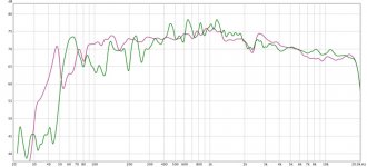
it was just a pointer. useless one that was but ok I was curious about how today's nearfield results compared with those I got at the listening position a few days ago. I've adjusted them vertically to maximize overlap and I'm surprised how much agreement there is. The listening position results involved averaging seven measurements with the mic moved vertically between measurements. Both the nearfield and listening position results are based on frequency scans rather than the pink noise and the moving mic technique. Also, I smoothed the listening position results at 1/12 octave to match the inherently smoother nearfield measurement.
The listening position measurement shows more evidence of the dipole roll-off at low frequencies, as one would expect. Beyond that, I'm surprised by the similarity. It makes me wonder whether I might learn something useful by taking a few nearfield measurements at different vertical locations along a planar driver, averaging them together to get something that reflects the driver as a whole, and then applying a theoretically derived adjustment to take into account 1) the dipole cancellation and 2) the behavior of a line source.
Why bother? Well, for one thing it's easier to get useful results at lower frequencies with the nearfield measurement. Also, I'm interested to know to what extent the tower is acting "ideally," meaning like a continuous 8' tall dipolar line source. Where it deviates, what's the cause?
Another idea is to take a series of measurements starting in the nearfield and then doubling the mic distance between measurements. These wouldn't be averaged--I'd be looking for trends in the results. Again, I'm interested to see the extent to which the towers behave according to simple models. I think I'll see different things depending on which mic height I choose so that's a bit of a fly in the ointment.
All of this is an attempt to figure out which frequency response glitches I should equalize away, and which I should leave alone, to end up with the best sounding result. I'm aware of the advice to equalize the first arrival response at high frequencies and equalize broad trends plus in-room peaks (not dips) at low frequencies. But getting clear first-arrival measurements at the listening position--results that aren't hyper-sensitive to mic position--is not trivial, especially over a wide frequency range. The moving mic technique is very reproducible and has yielded the best equalization results so far. But, I'm guessing that I might be able to do even better if I could learn my speakers' personalities by measuring them in several ways and determining which features appear under which measurement conditions. This is particularly important to me because I want the speakers to work well over a very wide range of listening positions, even if I still have one sweet spot that might get special treatment.
Few
Attachments
Last edited:
I played with some of the ideas in the previous post. After several variations I decided these results may be the easiest to interpret. Here are the conditions:
1) planar magnetic only (no woofers)
2) 1 KHz low pass on midrange
3) 50 Hz high pass on midrange and tweeter
4) rough attempt to equalize the nearfield response with mic centered over tweeter using only IIR filters
5) an 8 cycle time window was applied to all measurements
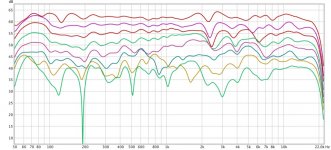
I started with the mic as close as possible to the grill cloth and made a frequency scan measurement. I then doubled the mic-diaphragm distance, and made another measurement. Rinse and repeat...
The measurement distances were 1", 2", 4", 8", 16", 32", 64", 128"
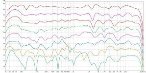
Two graphs of the same data are presented. The second graph just displaces the plots vertically in case it's easier to see some of the details that way. The first plot shows only the vertical displacements that were there in the measurements.
What's to be made of these results? Well, over much of the upper range it seems the response drops roughly 3 dB with each doubling of the distance as one might expect of a line source. As the mic moves farther away the reduction in response below about 1 KHz becomes more visible. This is a result of the dipole cancellation, which won't be as obvious with the mic right up next to the diaphragm. I expected the drop-off to be more obvious below 1 KHz once the mic was more than ~1 meter away, though. Too much room contribution to see it clearly? Something wrong with the measurements?
To be clear, I'm not suggesting this nearfield equalization approach is the way to achieve the best result at the listening position. I just found it easier to see the trends if the nearest measurement was made fairly flat as a starting point.
By the way, I found I couldn't equalize the glitch around 2.5 KHz so I think it's an interference effect. If I tried to fill in the dips it made no difference or even aggravated the problem. This is the same frequency at which I saw a ridge in the CSD waterfall plot. I haven't nailed down what's interfering with what yet but it seems not to be a resonance.
Few
1) planar magnetic only (no woofers)
2) 1 KHz low pass on midrange
3) 50 Hz high pass on midrange and tweeter
4) rough attempt to equalize the nearfield response with mic centered over tweeter using only IIR filters
5) an 8 cycle time window was applied to all measurements
I started with the mic as close as possible to the grill cloth and made a frequency scan measurement. I then doubled the mic-diaphragm distance, and made another measurement. Rinse and repeat...
The measurement distances were 1", 2", 4", 8", 16", 32", 64", 128"
Two graphs of the same data are presented. The second graph just displaces the plots vertically in case it's easier to see some of the details that way. The first plot shows only the vertical displacements that were there in the measurements.
What's to be made of these results? Well, over much of the upper range it seems the response drops roughly 3 dB with each doubling of the distance as one might expect of a line source. As the mic moves farther away the reduction in response below about 1 KHz becomes more visible. This is a result of the dipole cancellation, which won't be as obvious with the mic right up next to the diaphragm. I expected the drop-off to be more obvious below 1 KHz once the mic was more than ~1 meter away, though. Too much room contribution to see it clearly? Something wrong with the measurements?
To be clear, I'm not suggesting this nearfield equalization approach is the way to achieve the best result at the listening position. I just found it easier to see the trends if the nearest measurement was made fairly flat as a starting point.
By the way, I found I couldn't equalize the glitch around 2.5 KHz so I think it's an interference effect. If I tried to fill in the dips it made no difference or even aggravated the problem. This is the same frequency at which I saw a ridge in the CSD waterfall plot. I haven't nailed down what's interfering with what yet but it seems not to be a resonance.
Few
Attachments
Well if you know the voltage sensitivity per pascal you have a genuinely useful reading.
As for your 2.5 khertz anomaly. Change some thing radically in the path between the mic and the driver. Sometimes a placement of a part of thick towel or felt in the edge of the emit g surface of the driver will lead you to know if it's a reflection or an actual response bump.
If it disappears in the far field measurements it''s a reflection.
And a bit of wisely chose absorb time material in the right place works wonders design in taming the response of a wide bandwidth driver.
Thanks for the suggestion, Mark. So far I've been focused on linear distortions, except for those two quick distortion plots I posted. For that reason I haven't pursued absolute sensitivity measurements. They need to be included at some point, if only so others have some idea what they might expect for their own designs.
I did a sequence of nearfield measurements in which I kept the mic centered left-right over the tweeter, but moved the mic vertically over a range of a bit over a foot. I wanted to see if all parts of the driver were behaving similarly or whether, for example, the parts closer to the ends show effects from being clamped at the ends. I didn't post the results because the measurements looked very similar at all vertical mic positions. I bring this up as more background for getting to the bottom of the 2.5 KHz glitch. Also, if you look at the sequence of measurements taken at progressing greater distances from the diaphragm, the 2.5 KHz feature first becomes a clearer dip and then seems to fill in at greater distances. So I'm getting increasing convinced that it's a reflection, as you say.
The wavelength at 2.5 Khz is about 135 mm. To create a notch the reflected wave needs to be out of phase which implies a path length difference (direct vs. reflected paths) of ~69 mm or some odd multiple of that. I was first thinking the reflection might be from a structure behind the diaphragm but I don't think the distances work out to support that. It must be a reflection from the frame that the diaphragm is attached to, or the edge of the overall tower structure. I guess a mic movement left or right, rather than vertically ought to help verify that. There's not a ton of room to add sound absorbing material.
But...come to think of it, it could be from the frame the grill cloth is wrapped around! That would be particularly easy to figure out! The grill cloth frame is magnetically attached to the towers so removing the grills is a 3 second job. I beveled the inside edges of the grill frame but perhaps that's not getting the job done.
Now I wish I were still at home so I could do a quick test...
Few
A FEW more tests indeed. I've tracked down the reflections, I think.
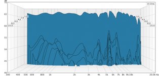
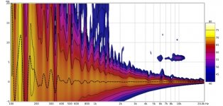
I went down the wrong path at first but it wasn't too long a detour. I made measurements with every possible combination of front and back grill installed and removed. Removing them seemed to help the 2.5 KHz problem I posted about, but I still had some grunge around 6.5 KHz in the waterfall CSD plot (first attached graph) and wavelet-based spectrogram (second graph). The spectrogram also shows a clear reflection at 6 ms so I moved the speaker farther from the back wall for subsequent measurements. All measurements posted were done in the nearfield.
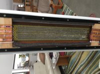
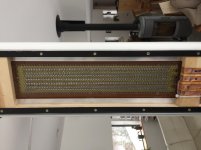
So I pulled out some adhesive-backed felt I bought long ago from McMaster-Carr and installed it behind the planar driver, lining the inside of the frame. The photos show the rear of a panel without the felt and then one with the felt installed. I've chased my tail too many times trying to convince the uploads to appear with the desired orientation so I apologize if the photos are rotated. The additional felt should be clear in any case.
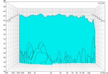
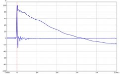
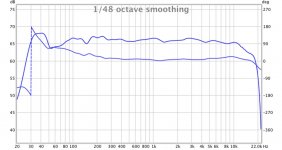
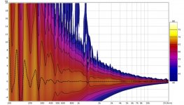
The felt really cleaned up the 6.5 KHz junk. I was even able to reinstall the grills, front and back, without the old 2.5 KHz problem reappearing. I had to re-equalize to compensate for the few dB lost at high frequencies because of the grill cloth, but once that's done things don't look too bad in the time domain. The impulse and step look pretty good considering I've not used any FIR filters and I just tweaked the equalization by hand (REW's optimized filters weren't working well when imported, for some reason). By eliminating the 50 high pass from the planars I was able to reduce the effect of the low frequency roll-off on the step response. The planars will cut off around 200 Hz in practice anyway, I just wanted to see what the native step response looks like. The magnitude and phase responses are shown with 5-cycle windows applied. I'll toss in the final wavelet-based spectrogram, taken with felt and grills in place, just to close things off. A careful look reveals that the felt did its job and the grills seem not to be doing too much other than attenuating the high frequencies (and damping the very low frequency diaphragm resonances as a bonus).
So I'm calling this progress. Doing the nearfield measurements has helped me track down some problems I had a hard time seeing with all the complications that accompany the farfield measurements. Now I need to invest in more (very expensive) felt so I can treat all the panels and then I can see what all this yields at the listening position.
Few
I went down the wrong path at first but it wasn't too long a detour. I made measurements with every possible combination of front and back grill installed and removed. Removing them seemed to help the 2.5 KHz problem I posted about, but I still had some grunge around 6.5 KHz in the waterfall CSD plot (first attached graph) and wavelet-based spectrogram (second graph). The spectrogram also shows a clear reflection at 6 ms so I moved the speaker farther from the back wall for subsequent measurements. All measurements posted were done in the nearfield.
So I pulled out some adhesive-backed felt I bought long ago from McMaster-Carr and installed it behind the planar driver, lining the inside of the frame. The photos show the rear of a panel without the felt and then one with the felt installed. I've chased my tail too many times trying to convince the uploads to appear with the desired orientation so I apologize if the photos are rotated. The additional felt should be clear in any case.
The felt really cleaned up the 6.5 KHz junk. I was even able to reinstall the grills, front and back, without the old 2.5 KHz problem reappearing. I had to re-equalize to compensate for the few dB lost at high frequencies because of the grill cloth, but once that's done things don't look too bad in the time domain. The impulse and step look pretty good considering I've not used any FIR filters and I just tweaked the equalization by hand (REW's optimized filters weren't working well when imported, for some reason). By eliminating the 50 high pass from the planars I was able to reduce the effect of the low frequency roll-off on the step response. The planars will cut off around 200 Hz in practice anyway, I just wanted to see what the native step response looks like. The magnitude and phase responses are shown with 5-cycle windows applied. I'll toss in the final wavelet-based spectrogram, taken with felt and grills in place, just to close things off. A careful look reveals that the felt did its job and the grills seem not to be doing too much other than attenuating the high frequencies (and damping the very low frequency diaphragm resonances as a bonus).
So I'm calling this progress. Doing the nearfield measurements has helped me track down some problems I had a hard time seeing with all the complications that accompany the farfield measurements. Now I need to invest in more (very expensive) felt so I can treat all the panels and then I can see what all this yields at the listening position.
Few
Attachments
-
 CSD waterfall NF no grills NFeq.jpg83.4 KB · Views: 255
 -
 wavelet spect NF no grills NFeq.jpg120 KB · Views: 262
 -
 IMG_0441.jpg755.2 KB · Views: 278
 -
 IMG_0442.jpg539.5 KB · Views: 283
 -
 felt waterfall grills new eq.jpg110.7 KB · Views: 268
 -
 impulse step felt grills new eq.jpg59.1 KB · Views: 111
 -
 mag phase felt grills new eq.jpg82.1 KB · Views: 119
 -
 wavelet spect grills felt.jpg126.1 KB · Views: 114
This thread on line arrays is very informative. I recommend it if you have an interest in non-point source speakers. I bring it up here because I wondered whether I could "perfect" the nearfield performance and then apply theoretically derived corrections for 1) the range of wavefront arrival times and 2) dipole cancellation that shows up in the farfield. Might that be an alternative to devising farfield measurements that correlate with listeners' perceptions?
After much fiddling with the equalization I was able to get decent looking impulse and step responses at 2 m from the left speaker with the mic positioned vertically at half the tower's height. The thread I mentioned earlier explains that compensating for the farfield frequency response trends (relative to an ideal nearfield radiator) automagically also fixes the impulse and step responses.
What I found was that after laboriously achieving pretty SPL, impulse, and step response graphs with the mic at mid-height, if I moved the mic down a bit, all hell broke loose.
I guess that's as expected, according to the theory, but it's unsettling when you're aiming for a practical collection of settings that will work for listening to music outside a nano-sized listening volume.
To aggravate things further, when I tried to apply the left channel settings to the right channel I discovered another anomaly. Haven't I already been through this? I'll spare everyone the details and cut to the punch-line. I had mis-wired one of the four tweeters in the right channel so it wasn't contributing to the mix. With that fixed, the left-right balance is a bit more reasonable.
Plus I found enough wool felt in the ol' shop so that I could fully treat both speakers. So at least I can call it a day having completed that job.
I'm pleased with the nearfield progress, still unsure how to take advantage of it in the farfield, and enjoying the sound of music even while knowing there are technical details to iron out.
Maybe I should build a 1 cubic mm plasma speaker with 110 dB SPL capability and flat frequency response and call it good?
Few
A little reading taught me how flat the group delay of a Bessel filter is within and near its passband. That explains why my low-passed midrange plus unfiltered tweeter approach doesn't add significant phase distortion.
I selected a Bessel low-pass for the midrange to minimize the phase anomalies the filter would introduce but I guess I underestimated how well it might work. Pretty slick, really. It makes the planar midrange-tweeter assembly act almost like a single fullrange driver but with nicely frequency-independent directivity and without latency-inducing FIR filters. Of course "full range" should be in quotes because I think the distortion down below 200 Hz or so might preclude that label. I haven't done a quantitative distortion measurement---meaning one with known SPL---I just noticed that the distortion products seem to increase a bit below 200 Hz when the system is measured at a medium volume (how's that for quantitative?).
So I'm left feeling a version of my DIY planar magnetic mid-tweeter could be useful in a design that's simpler than the one I've ended up with. If I were to start from scratch I could certainly design an easier to fabricate version that retains the key features. Still refining the one I have, though. Maybe I'll build a desktop version to straddle a computer monitor. In that context it could work down to 100 Hz or below with no problem, I suspect. Just stuff a small subwoofer under the desk.
Few
Plate thickness = 0.0625" (1/16")
1/4" diameter holes, staggered. I think the open area was ~60% but don't quote me on that. Why do you ask? Source of reflections and resonances?
No it's for a quick think on the motor force calculation.
I can see the magnets, and now that I have a few of the dimensions in the photo the others are simpler to deduce.
It's a single ended motor? Magnets on one face of the diaphragm?
I wondered about the membrane did I read correct , that you laminated the kapton to the pre cut Aluminum of course. Then laminated all sides with syreen wrap ? Polyethylene soft thin foil ? Could you get the tension high enough ? Resonance must be super low because if it ? Thought about that same idea never excetuted so very cool to see , makes the kapton moves more uniformly ?
- Home
- Loudspeakers
- Planars & Exotics
- DIY planar magnetic + open baffle woofer array