Yes, the reduction of boundary reflections and more uniform SPL with distance were two key reasons why I went with this design. My house has a highly reflective interior and there's a huge range of listening distances that I'd like to cover, realizing things can't be optimized for all distances simultaneously. A very tall dipole was my attempt at a solution. Once the 9' tall Christmas tree is gone I can test my idea of aiming the dipole null at the point along the reflective side wall that would otherwise send a big reflection at the main listening spot.
When I did the conventional ground plane measurements the mic was about 2 m away from the speaker and I tilted the speaker to aim its main axis at the mic. I'm sure I didn't do it very accurately, though. In any case, I ended up with a much noisier impulse response than I was getting with the mic a few feet in the air. Lots more "junk" after the main impulse and before the first clear reflection. That was, of course, the opposite of what I was going for.
The measurements I made using the large wall of windows as a vertical "ground plane" yielded much better results. Less hash after the impulse and the magnitude response was quite free from reflection artifacts above the frequency where room modes are going to dominate no matter what you do.
So maybe I just did a poor job with the ground plane attempt. You commented that you find it most useful below 500 Hz. That's not what I would have expected. The ground plane approach won't eliminate room modes, so I was thinking of it being most useful at higher frequencies where it could buy a bit more reflection-free time after the arrival of the main impulse.
I used to have some Radio Shack PZM microphones that were ideal for ground plane measurements (apart from their unknown frequency response!) but I've just been putting the business end of my mic as close as possible to the flat surface and crossing my fingers.
Few
My comment about ground plane being useful below 500 hertz should have been a little clearer. Useful if done outside as a true ground plane measurement.
You can do wide range ground plane measurements. But it is hard to interpret them when comparing them to other methods.
Like I said. You picked the deep end of the measurement pool to start in.
But your at least floating and not sinking!
The tip I gave you about doing nearfield measurements and then adjusting your farther measurements mic position until you get the closest results id pretty much the way to learn what works best.
And you are completely right in trying to find the place placement within your current listening room. Not so nice for family to be listening to test signals!
I use a test box from Smith and Larson. It can do a variety of measurements using a great deal of different test signals. Like the LMS system it can send a discrete sine wave and then setup a twin t filter to reject any other noise. Great for getting good measurements within a not so great measuring environment. But oh what a pain to be listening to! A 100 plus point or even a 512 point measurement takes forever and gives you awesome resolution in your results. But it is pretty awful to be near it.
Ah, got it. Yes outdoor ground plane measurements would be great. I live in the rural part of a rural state that'll be snow-covered until mid-April so I'll have to do what I can indoors for now.
My goal is to optimize the miniDSP settings for best psychoacoustic effect in my particular room, rather than to optimize the engineering of the woofers, for example, so I think I can make do with in-room measurements. I just need to accumulate more experience measuring speakers that don't act like point-sources.
Thanks for your advice, Mark! It's helped me clarify my thinking.
Few
What a lovely looking pair! Beautiful!
If I may add a few thoughts... measuring an array up close is never going to work. You need distance to get the sound to integrate, especially on the bass arrays. Running around the room to get reflection free measurements will also be near to impossible.
What I would do is set them up for your listening position and take measurements there. With these tall arrays I'd like to be at least 3 meter from them.
As you have chosen open baffle, play with toe-in/out and see what it does to reflection levels in your measurements.
Are you using REW? If so, check the impulse for blips after that impulse spike, and check the next tab, the filtered IR set to "dB FS" in the upper left corner.
What you're looking for is the magnitude of the reflections. Now this graph won't tell the whole story unless you use it's filtering capabilities, it will get you started.
It should look something like this:

A nice, well defined peak with a big drop immediately afterwards. Try to have those reflections down as far as you can, preferably more than -20 dB for the first ~20 ms. These are measurements from my (sealed) full range line arrays.
Keep in mind that the stuff behind the microphone can also reflect back. You need some space behind the microphone. I didn't have that space behind the listening position and used damping panels to absorb that energy. I also needed a damping panel on a side wall, as I do not have that dipole magic helping me out.
Once you have that lower reflected energy (we still didn't see the lower end, as that would require to use filters in the filtered IR tab) we can see how the measurement looks.
Personally I don't use the normal gating. There's a valid reason for that. A high note only lasts a couple of milliseconds. So everything after that isn't the high end of the speaker anymore. Actually, the high end is already done and you're only adding the room influence and frequency decay into the measurement. It would be different if we had an actual anechoic room to play with.
I use another form of gating, called a frequency dependent window. This gates the measurement very short for high frequencies and gradually longer for longer, lower frequencies. This leaves out way more room influences. The frequency dependent window can be found behind the IR window button, you can set it in cycles or width in octaves. Don't use any gating combined with this.
Be advised REW is smoothing these frequency dependent windows if I compare it to some other tools.
Base your correction, be it PEQ or FIR on a 6 cycle window for starters. Do not use 6 cycles for phase correction though, you would be trying to EQ room positions, that's not going to work in a large area. Start simple and EQ the frequency curve when viewed with that frequency dependent window of 6 cycles. Every plot without that window set will automatically look way better, but more important, your sound will improve.
There are other ways to try and exclude the room in your measurements. There were some excellent examples in the RePhase thread only days ago. Look here for more info:
http://www.diyaudio.com/forums/multi-way/221434-rephase-loudspeaker-phase-linearization-eq-fir-filtering-tool-141.html#post4920173
I hope this gives you some new alternatives to try. It worked very well for me as another line array builder. Line arrays behave different, your open baffle will behave different from my sealed arrays. You've got to find a way that works for you. Maybe this helps. My thread as linked is full of my personal journey trough measurements and DSP, it may be a fun read for you. It is huge though. Sorry for that") .
.
If I may add a few thoughts... measuring an array up close is never going to work. You need distance to get the sound to integrate, especially on the bass arrays. Running around the room to get reflection free measurements will also be near to impossible.
What I would do is set them up for your listening position and take measurements there. With these tall arrays I'd like to be at least 3 meter from them.
As you have chosen open baffle, play with toe-in/out and see what it does to reflection levels in your measurements.
Are you using REW? If so, check the impulse for blips after that impulse spike, and check the next tab, the filtered IR set to "dB FS" in the upper left corner.
What you're looking for is the magnitude of the reflections. Now this graph won't tell the whole story unless you use it's filtering capabilities, it will get you started.
It should look something like this:
A nice, well defined peak with a big drop immediately afterwards. Try to have those reflections down as far as you can, preferably more than -20 dB for the first ~20 ms. These are measurements from my (sealed) full range line arrays.
Keep in mind that the stuff behind the microphone can also reflect back. You need some space behind the microphone. I didn't have that space behind the listening position and used damping panels to absorb that energy. I also needed a damping panel on a side wall, as I do not have that dipole magic helping me out.
Once you have that lower reflected energy (we still didn't see the lower end, as that would require to use filters in the filtered IR tab) we can see how the measurement looks.
Personally I don't use the normal gating. There's a valid reason for that. A high note only lasts a couple of milliseconds. So everything after that isn't the high end of the speaker anymore. Actually, the high end is already done and you're only adding the room influence and frequency decay into the measurement. It would be different if we had an actual anechoic room to play with.
I use another form of gating, called a frequency dependent window. This gates the measurement very short for high frequencies and gradually longer for longer, lower frequencies. This leaves out way more room influences. The frequency dependent window can be found behind the IR window button, you can set it in cycles or width in octaves. Don't use any gating combined with this.
Be advised REW is smoothing these frequency dependent windows if I compare it to some other tools.
Base your correction, be it PEQ or FIR on a 6 cycle window for starters. Do not use 6 cycles for phase correction though, you would be trying to EQ room positions, that's not going to work in a large area. Start simple and EQ the frequency curve when viewed with that frequency dependent window of 6 cycles. Every plot without that window set will automatically look way better, but more important, your sound will improve.
There are other ways to try and exclude the room in your measurements. There were some excellent examples in the RePhase thread only days ago. Look here for more info:
http://www.diyaudio.com/forums/multi-way/221434-rephase-loudspeaker-phase-linearization-eq-fir-filtering-tool-141.html#post4920173
I hope this gives you some new alternatives to try. It worked very well for me as another line array builder. Line arrays behave different, your open baffle will behave different from my sealed arrays. You've got to find a way that works for you. Maybe this helps. My thread as linked is full of my personal journey trough measurements and DSP, it may be a fun read for you. It is huge though. Sorry for that
.Yes, tall is a good word for them. I had the same reaction when I started assembling the frames to hold the four planar magnetic panels. And then I realized I needed legs and feet, besides. Ugh.
Wesayso:
Thanks for the thorough contribution. I started reading that rePhase thread awhile ago when I began to familiarize myself with the program. I haven't yet gotten very far through it, though, so I'll have to focus my efforts on the description of your adventure.
Also, I had read somewhere that REW has a frequency dependent window but when I didn't see it among the other window options I forgot to follow up on it. Your hints as to where to find it will be very helpful.
My main listening seat is about 9 m from the speakers, as you suggested. I'll need to wait for Christmas to pass before I can experiment more seriously with speaker angle and its effect on side wall reflections. The Christmas tree is standing precisely where the worst side reflection will come from.
I was a little confused by your comments about using filtering in the IR response. Were you suggesting that filters be used or not? I don't have any experience with impulse response filters so that may be the cause of my confusion. Perhaps the thread you linked to will answer my questions. In any case, thanks again for the advice.
On a more general note, my sense of Floyd Toole's suggestions (without going back to read his book and check my memory!) is that some form of reflection-free measurement (such as gating) should be used above around 400 Hz +/-. Below that frequency room modes should be thought of as part of the system's response so ungated measurements are necessary. That was the philosophy I was using as a starting point. I'd be interested to hear whether others have found it to be a good approach or whether there are pitfalls I should be aware of.
Few
Hi Few,
I was commenting about the filtered IR tab. An IR is a representation of the measured response, a chosen interpretation of it. There's much more info hidden in it than an IR graph shows. It can be dissected to see that info by using filters on it. You can find some on the left bottom in the filtered IR tab. It lets you set a filter to see the data in a narrow filtered section of the IR.
Just like you can gate it to exclude later reflections. Only we get to see a very narrow slice. For instance 8000Hz 1/3. That will show you what's really going on around 8 KHz. If you click in the IR tab next to it, you can even see the cycles of information at that frequency.
In the filtered IR tab it shows you the real attenuation at that frequency, not the interpreted overall representation. Realise it's hard to explain for me as it would be easier if we were sitting next to each other and I could show you this stuff in real time.
Instead of gating before the first reflection I suggested to use the frequency dependent window.
What would happen if you gate an IR before your first big reflection? Say the first big reflection happens at 4 ms. That would mean you'd see about one cycle of usable info at 250 Hz. But lets see how many cycles you have at 1 KHz. Once cycle at 1 KHz lasts 1 ms.
This would mean the 4 ms gated measurement has 4 usable cycles at 1 KHz.
Let's move even further up in frequency, what happens at 8 KHz. One 8 KHz cycle would last 0.125 ms, meaning you could finish 32 cycles of 8 KHz in that 4 ms gated time frame. But REW doesn't use an infinite number of cycles in it's measurement. So actually you are looking at data that shows what happens long after 8 KHz stopped "singing".
So at 250 Hz the speaker just started to sing, at 1 KHz we may see some useful data and at 8 KHz its supposed to be finished long ago. Meaning at this frequency you see what the speaker has done and all of the little stuff that happens afterwards.
If we take Toole's hint, we would need about a 10 to 12 ms of reflection free zone before we see any useful data at 400 Hz (If I want to see about 5 to 6 cycles).
What's the difference with using a frequency dependent window?
At 250 Hz, using 6 cycles the gating window would be 24 ms. At 1 KHz that window would be 6 ms long. And at 8 KHz the window that is used is is only 0.75 ms long.
So look at it as a sliding window. To see the early response of that wave front. You are gradually letting more of the room into the measurement as you go down in frequency. But the correction based on this window is acting where it happens, not long after that wave front stopped "singing".
That blip in the IR we see as a reflection (the reason we gated at 4 ms), at what frequency is that one happening? We would need to look at the spectrogram window to find it there. Or use those 1/3 octave filters again in the filtered IR tab to get a clue. Chances are it's only happening at a higher frequency.
See how the frequency dependent window basically lets you look inside the measurement and shows the early wave front as it happens? (at it's origin) Gradually you let the room into your analysis.
Now if you succeed in my proposed clean up of the IR for the first 20 ms, we would surpass that target Toole mentioned.
If we get a clean first 20 ms, we would have a clean 6 cycles of data down to 300 Hz.
I'll tell you up front, it's not that easy to hunt down reflections, but every bit of clean up you can do there helps. The less DSP is needed to get to our goal.
"The speakers will only sound as good as the room they are in" is often said. So make sure your speakers work with the room.
I found out why I wasn't seeing the frequency dependent windowing in Room Eq Wizard. It wasn't there in the version I was using. I just updated and now there it is.
During my effort to figure out what I was missing I ran across a YouTube video showing the limitations of the frequency dependent windowing. The poster says to watch out for a follow-up video on the "right" way to isolate the speaker measurements from room effects but I can't find any such follow-up. I'll be interested to see what magic he has to offer. As it stands, I think the frequency dependent window still has utility if its limitations are borne in mind; just like every other tool. The main message from the YouTube video (for those who don't want to sit through the rather slow delivery) is that high Q resonances, which by definition involve many oscillation cycles, will be falsely shown as less prominent than they really are if typical settings are used for the frequency dependent windowing is used.
Has anyone seen a time domain approach for artificially flattening (erasing) distinct room reflections from an impulse response in an effort to extend the useful duration of the measurement? Obviously this would introduce some artifacts but perhaps one could learn to identify and see around them a bit?
Thanks again, wesayso, for the continued advice. I'm comfortable with fourier transforms and interpreting measurements in the frequency and time domains, but I had entirely missed some REW features that you brought to my attention. I agree that my dipoles should reduce the side reflections but of course they do so at the expense of adding rather prominent rear wall reflections. I will be very interested to see how well I can tame those.
The moderators moved this thread to the planar and exotic realm. I hope it doesn't cause any confusion.
Few
I see that you are struggling to find a way to obtain low frequency response info for your OB panel. The problem is typically that, in the lowest frequencies of interest (e.g. 500Hz and below), a gated measurement will be reaching its limits and will be of poor (e.g. low) frequency resolution (e.g. 100-200 Hz resolution), and an in-room measurement is often unintelligible because of room modes.
John Kreskovsky put forth a great measurement-based method for modeling the low frequency response from an open baffle system HERE. You need to take at least a front nearfield measurement. It looks like you did this already from an earlier post. A nearfield is typically done with the mid very close to the front of the driver cone (e.g. 1 inch or less) but your 8" Dayton woofers may have a phase plug (I am not sure of the exact model) so just get as close as you can to the cone and next to that if you have to. You can optionally take a nearfield at the rear with the mic somewhere very close to the cone. From these two measurement, or even just the front measurement in a pinch, you can synthesize the OB response by using software to add delay to the "rear" measurement and inverting its phase. Then you sum the front measured data and the processed rear data (inverted and delayed). The result is the OB response, because this is essentially what is happening in the air - the two wavefronts are combining (adding).
You will need to calculate the relative delay that will occur for whatever position (on or off axis and how far away from the front baffle into the room). You can do this based on geometric information (e.g. meters from listening position to center of driver, at the front and rear) and the speed of sound (meters per second). Take the distance to the rear "source" and subtract the distance to the front "source". Divide the result by 344 m/s to give you the time in seconds. This is the delay that you must apply.
You can use one of the spreadsheets in my Active Crossover Designer tools to do this, or another software of your choosing. You should see the familiar OB response pattern with additional low frequency droop from the Q of your driver in its open baffle loading, which is approximately the "free-air" response.
When you can't measure the speaker outside (it's cold in Maine in the winter, eh?) then this is a good way to get a close approximation to the LF response.
Thanks, CharlieLaub, for the input. I made reference to precisely that approach in post #13 but didn't at that time have a convenient way to implement it. I'll definitely look into your Active Crossover Designer tool.
But then there's still the question of what the target should be. If the room is part of the system below x Hz, then why not include all the ugly room modes and equalize the overall response to the extent that is practical (do not try to fix the deep dips or the ones that show up only in unimportant locations)?
Or is the result more satisfying if you equalize only the driver+enclosure glitches, and let the room have its way?
My gut tells me that at low frequencies there's no point pretending the room isn't going to make an enormous difference and that it's best to aim for good in-room response---in other words, include the room modes. At higher frequencies, where the wavelengths are short and response varies dramatically over a distance of inches, it's better to work from a quasi-anechoic measurement. Having said that, I'm very interested in hearing what others have found. I don't have that much confidence in my gut.
Few
Nice builds, rewind.
I'm currently wrestling with an electrostat/dynamic hybrid, and am getting pretty decent results using a RSS265HF-4 from 80-300 hertz.
When not doing deep bass, that driver is a very good midbass bridge to the smallish electrostatic panel I'm trying out.
I'm currently trying the 10"woofer on a mini baffle, somewhere @ 30 degree tilt up.
I figure this aims the more directional cone aberrations away from me, front and back.
This may be the reasoning behind some of Stig Carlsson's cooler looking designs.
Interesting that I moved from planars to 'stats, as you went the other way.
Thanks, CharlieLaub, for the input. I made reference to precisely that approach in post #13 but didn't at that time have a convenient way to implement it. I'll definitely look into your Active Crossover Designer tool.
But then there's still the question of what the target should be. If the room is part of the system below x Hz, then why not include all the ugly room modes and equalize the overall response to the extent that is practical (do not try to fix the deep dips or the ones that show up only in unimportant locations)?
Or is the result more satisfying if you equalize only the driver+enclosure glitches, and let the room have its way?
My gut tells me that at low frequencies there's no point pretending the room isn't going to make an enormous difference and that it's best to aim for good in-room response---in other words, include the room modes. At higher frequencies, where the wavelengths are short and response varies dramatically over a distance of inches, it's better to work from a quasi-anechoic measurement. Having said that, I'm very interested in hearing what others have found. I don't have that much confidence in my gut.
Few
If you want to EQ out the room response, that is fine - your call. I would first create the free-field OB response using the method I mentioned and get the low end corrected (e.g. add boost). Then you can go back and take an "in room" measurement at your listening position and see what that looks like.
The in room response is position dependent. If you are satisfied to optimize a single location, then you can try to EQ the response at your listening position. This might work at 100Hz and above with your OB panels - they are probably not going to have all that much headroom to fill in any dips below that. Another approach is to move the loudspeakers to a new place within the room so that cost locations within the room have a similar (and hopefully even) response, but this might mean the loudspeakers end up out in the room. Yet another approach is to use a subwoofer crossed as high as possible and located very near your listening location - like right behind the sofa or chair and and with the driver 1m above the floor. This puts your listening position in the nearfield of the subwoofer, which drastically reduces the relative contribution of the dreaded room modes.
Last edited:
I found out why I wasn't seeing the frequency dependent windowing in Room Eq Wizard. It wasn't there in the version I was using. I just updated and now there it is.
During my effort to figure out what I was missing I ran across a YouTube video showing the limitations of the frequency dependent windowing. The poster says to watch out for a follow-up video on the "right" way to isolate the speaker measurements from room effects but I can't find any such follow-up. I'll be interested to see what magic he has to offer. As it stands, I think the frequency dependent window still has utility if its limitations are borne in mind; just like every other tool. The main message from the YouTube video (for those who don't want to sit through the rather slow delivery) is that high Q resonances, which by definition involve many oscillation cycles, will be falsely shown as less prominent than they really are if typical settings are used for the frequency dependent windowing is used.
Has anyone seen a time domain approach for artificially flattening (erasing) distinct room reflections from an impulse response in an effort to extend the useful duration of the measurement? Obviously this would introduce some artifacts but perhaps one could learn to identify and see around them a bit?
Thanks again, wesayso, for the continued advice. I'm comfortable with fourier transforms and interpreting measurements in the frequency and time domains, but I had entirely missed some REW features that you brought to my attention. I agree that my dipoles should reduce the side reflections but of course they do so at the expense of adding rather prominent rear wall reflections. I will be very interested to see how well I can tame those.
The moderators moved this thread to the planar and exotic realm. I hope it doesn't cause any confusion.
Few
I've endured the video, that was a trip... I've said as much in my first post. REW's frequency dependent window is smoothed (about a 1/6 smoothing at 5/6 cycles) compared to other programs implementation of a frequency dependent window.
But don't despair, it will prevent you from using high Q corrections which aren't a good idea anyway. He basically tried to imitate a very bad driver break up, I try to avoid using drivers that bad by looking at their measurements before I choose to use that one.
The rest of the video was hard to get trough
. He was upset with smoothing as well, you see changes happening. Oh boy, if you don't know what you're looking at it gets quite complicated fast I assume .Using the frequency dependent cycles doesn't exclude you to still have an eye open for the other graphs, does it? It's one of the things to use, I always combine it with looking at the IR itself and the very early waterfall graphs. As well as a spectrogram window as without each I still don't know what's happening.
But that doesn't make this a bad method. It only means he saw REW is smoothing frequency dependent windows. I can agree with that.
I see we are back at near field measurements again in the follow up responses. Good luck with that on an array, it's just not going to work i.m.h.o.
Think about what an array of drivers does, especially after reading the posts I linked to in the RePhase thread. Each driver in that array will have it's own distances to reflecting objects, so the reflections will be different for each driver in the array. As you get further away the sum of the array will as a result average out those reflections, except for big vertical planes. As there the drivers will have very similar distances to the reflecting objects.
This is the reason an array behaves different from a single driver in a room. It is the reason you won't see a strong floor or ceiling reflection. But you will still see side wall reflections if and when they happen.
If you can get those as low as possible you stand a very good chance of getting great results with an array and using the frequency dependent window.
Personally I don't use REW's frequency dependent window as I use FIR correction. DRC-FIR is my software of choice as that allows me to do some time corrections as well. Early on I compared the windows I got in DRC to the ones found in REW and noticed the smoothing happening in REW's FDW.
Here's what I found (not a measurement of my array, this one is used with subs underneath):
Starting from here I looked into the differences between REW's frequency dependent window and the method used by DRC-FIR. They obviously differ in implementation. But that doesn't make frequency dependent windowing a bad idea. You just have to know and learn the limitations of the programs you use.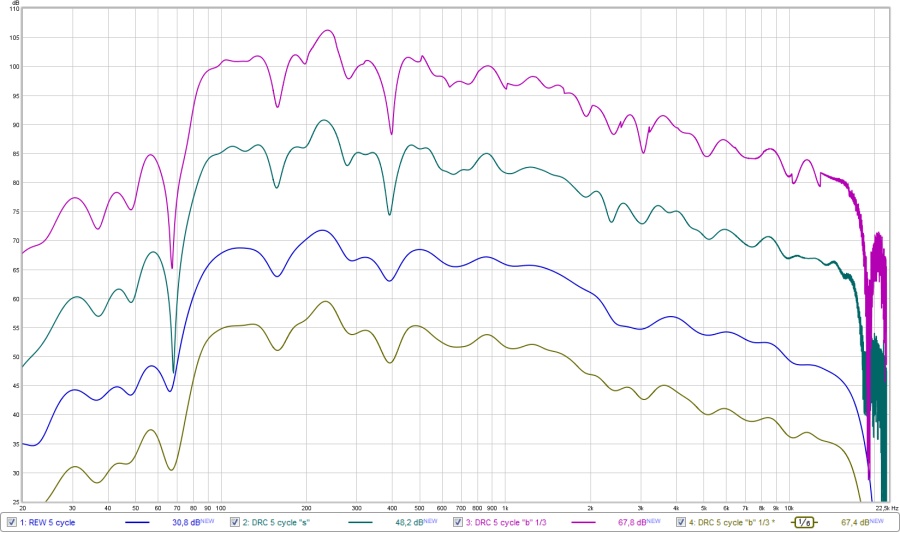
The top graph is DRC doing a 1/3 octave 5 cycle window. (MPPrefilterType = b and MPBandSplit = 3)
Second one is DRC's sliding window (my favourite)
Third graph is REW's 5 cycle window
Fourth graph is DRC's 1/3 octave 5 cycle window we saw, but smoothed 1/6 octave.
In hindsight I see why, knowing the result of the first type of a frequency dependant window that was introduced in REW. Well, this satisfies all of my curiosity.
In my opinion it would be a bad idea to use a bigger number of cycles as it will include way more room into the measurement. You can get very good results with the shorter number of cycles, even when using REW. DRC-FIR is free and gives more resolution. I'm just not sure you can use it's FIR filters in your specific tools, the ones I use probably have too many tabs. Your equipment seems to have 9600 tabs at 48 KHz. This will limit the resolution of FIR filters.
Last edited:
- Home
- Loudspeakers
- Planars & Exotics
- DIY planar magnetic + open baffle woofer array