I did some equalization, aiming for the best response over a range of positions. All went pretty well until I tried to apply the settings to the other speaker channel in preparation for calling it day. It turns out I lost a connection to one of my tweeter conductors. It took some sleuthing to find the culprit but I narrowed it down to one of two connections. As Murphy's law would predict, they're both at the top of the tower.
So balancing on a step ladder I tried to fix the joint without pulling things apart. Copper soldered to aluminum, all on thin kevlar, with magnets trying to pull the soldering iron through the diaphragm---not fun. I've got things sort of limping along again but the resistance of the repaired connection is an ohm or two too high so I really need to fix it further. I'm quitting for today for fear I'll do something irreversible if I push on.
I haven't really played with toe-in yet so that's a good suggestion, Mark. I also need to try pulling the speakers farther from the wall and see how much the imaging changes. I can only do that when I'm home alone. Nobody else would tolerate these things 5 feet out into the room.
Plus I think I need to add in a room curve of some sort. They sound a bit hot on some recordings when equalized to a fairly flat in-room response. The problem is that different recordings sound so dramatically different it's hard to gauge what to use as a target. Life was easier with speakers that homogenized everything!
Few
What I have found over the years is that the better the speakers the more picky you end up being with the recordings that you end up keeping.
The gist of the Linkwitz piece was a gradual taper of the high frequency starting from about 2khertz down about 2 db at 20 kilohertz. It has been useful for my work and many people like it without my ever telling them. A flat response is usually to hot when properly summed in the listening position in front of two loudspeakers. And far to few people have come to that realization.
The gist of the Linkwitz piece was a gradual taper of the high frequency starting from about 2khertz down about 2 db at 20 kilohertz. It has been useful for my work and many people like it without my ever telling them. A flat response is usually to hot when properly summed in the listening position in front of two loudspeakers. And far to few people have come to that realization.
Ha. Yeah, the plumb bob was the first thing that came to mind. It wasn't very well damped (not surprisingly) so I had to gently bring it into contact with the paper bearing my angle marks in order to get it to settle down to a final position. A turntable is obviously a better long term solution but I was too eager to get some first measurements to take the time to assemble one. I figured the plumb bob would not be my main source of error so I went with it.
Few
Few
Sort of like buying a meter to tell you if you are hungry.
Toole and colleagues did important studies of dispersion on creating a retail speaker with anechoic tests. For sure, dispersion matters because it determines what gets to your ears and when and you should buy a speaker in light of that data and knowledge of your room's characteristics vis a vis the speakers' locations.
But you already have your room. Dispersion data adds nothing to what you can measure at your seat. Certainly should be measured and not, unlike other DML threads, done by guesswork.
Ben
Last edited:
Sorry Ben but I'm not sure I'm capturing the gist of your comment.
"Dispersion data adds nothing to what you can measure at your seat. Certainly should be measured and not, unlike other DML threads, done by guesswork."
"Dispersion adds nothing...but should be measured" is the part I don't follow. Can you clarify? Also, I'm afraid DML isn't ringing any bells for me. What does that acronym refer to?
"Dispersion adds nothing...but should be measured" is the part I don't follow. Can you clarify? Also, I'm afraid DML isn't ringing any bells for me. What does that acronym refer to?
Did you understand why dispersion matters when you are a manufacturer producing a good speaker (with good specs)? But when you have a speaker in place (or being placed) in your room, you are only interested in the outcome at your chair?
My sentence wasn't absolutely clear. I certainly approve of your efforts to measure the speaker even if am anechoic-like measure of dispersion doesn't mean much after you put the speaker in your room. Better would have been, "Dispersion data adds nothing to what you can measure at your seat. Certainly RESULTS FOR A DML SPEAKER should be measured and not, unlike other DML threads, done by guesswork".
Ben
I can't tell if you're actually asking me a question or whether your comments were rhetorical. In case it's a real question, here are my goals and priorities for this project:
I designed my speakers to work well in the particularly large and reflective room in which they were going to be placed. I built line sources so loudness would be more uniform throughout the long space and so that floor and ceiling bounces would be minimized. I built dipoles so I could reduce the contribution from the highly reflective side walls and because I was interested to discover whether they would create realistic-sounding bass. I also wanted to approximate constant directivity so that the reflections that remain sound something like the direct sound. I'm interested to learn whether better imaging and perceived spectral balance results.
So I am not only interested in the outcome at my chair; I am aiming for good sound throughout a large open-plan living room/dining room/kitchen and particularly good sound in the prime listening seat.
I've described using a combination of quasi-anechoic measurements and moving mic measurements that include the room. I expect first-arrival sound to have an impact on sound quality, and I built the planar drivers from scratch so I need to verify they're behaving properly. For those two reasons quasi-anechoic measurements are useful. The room is reverberant so I'm also making measurements that include the room contribution, hopefully without getting too preoccupied by comb filtering that happens only in narrowly defined locations. I sense from your comments you prefer one flavor or the other. For my purposes and self-education I want to see the results of both. I need directivity measurements to know whether my goal of constant directivity has been achieved. That's best done quasi-anechoically.
I'm not sure I've addressed your question about what I understood (if it wasn't rhetorical).
I still don't know what DML means so I can't address that part.
Few
Thanks for your not-small effort to explain your circumstances. Clear you have general scientific interests in your project as well as making it work in your particular space.
But let me re-state my point - if not applicable to you and others with commercial or scientific interests then for other DIYers interested in optimizing performance through measurements for their personal room. As they say in politics, "the only poll that counts is voting day".
Ben
But let me re-state my point - if not applicable to you and others with commercial or scientific interests then for other DIYers interested in optimizing performance through measurements for their personal room. As they say in politics, "the only poll that counts is voting day".
Ben
Did you understand why dispersion matters when you are a manufacturer producing a good speaker (with good specs)? But when you have a speaker in place (or being placed) in your room, you are only interested in the outcome at your chair?
You do realise that all the energy emitted from the speaker do add in some way or an other in the listening position? And the behaviour of the off axis together with the room has a significant impact on the perceived SQ?
Your statement is strange. Why does dispersion matter in production? Do you mean that it is a good aspect to measure to understand if the product is produces to specification?
//
You do realise that all the energy emitted from the speaker do add in some way or an other in the listening position? And the behaviour of the off axis together with the room has a significant impact on the perceived SQ?
Your statement is strange. Why does dispersion matter in production?/
Yes, of course, all the energy goes hither and yon. That's why the anechoic-like dispersion doesn't matter once you have your room to measure. Just measure in situ. For a lot of us, results at just a single seat is all we care about*. That's simple. For others, like Few, more locations to check.
If you are selling speakers, it is good to document dispersion (which is an important factor north of the low frequencies) for potential buyers with a range of different music rooms. But once you have your room and your speakers....
B.
*here and other threads (such as the wave-around-the-mic thread), question of best scientific method comes up. I think you just can't make it simple enough otherwise interpretation becomes problematic. So I work with a mic on a tripod in the same exact location all the time (otherwise occupied by my head). Doesn't address all questions I might have, but does answer some questions definitively.
Last edited:
You must be envious of that microphone taking up your listening space Ben!So I work with a mic on a tripod in the same exact location all the time (otherwise occupied by my head). Doesn't address all questions I might have, but does answer some questions definitively.
By DML are you referencing Distributed Mode Loudspeaker? Cuz FEW made a planar magnetic for mid to high frequency use. Not A DML.
Mark - same comment applies to sound sources of every sort. And more generally, to near-field measurements. Point is to measure performance where you sit, not in an open field, at one meter, or by taking manufacturers' claims at face value.By DML are you referencing Distributed Mode Loudspeaker? Cuz FEW made a planar magnetic for mid to high frequency use. Not A DML.
You're right that I unfairly lumped together something which seems to be pretty awful with something different but, um, related.
Ben
If these planar magnetic drivers behave anything like DMLs (thanks for the acronym clarification) then I've truly missed my target.
...Which provides a segue for this post. I decided to take a closer look at how the planar drivers are behaving. I've been reading up on Room Eq Wizard so this also provides an opportunity to apply some of what I learned. I'm going to post a bunch of nearfield measurements taken with the mic a few cm from the central conductor of one of my planar drivers, grill cloth in place, and with the "crossover" and equalization still applied. Some of these measurements are not super relevant but I'm going to toss them in for completeness. For example, I took a look at distortion just to see if it highlighted any nasty buzzes but since the measurement was done nearfield, the drive level was low and the distortion products are therefore unrealistically low. Nobody has asked for any detail on the design or construction of the DIY planar magnetic drivers so I don't know if these measurement details will be of interest to anyone. I'll throw them into the mix anyway---at least I'll have an easy-access record of my own results.
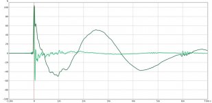
1) Impulse and step response. It looks fairly clean, but the large low frequency oscillation seems to correspond to the ~350 Hz peak seen in the magnitude response, not to the 150 Hz high pass crossover. I'm guessing it's a result of a 5.5 dB Q=2 peak I've added at 345 Hz in the miniDSP equalization. I added that based on measurements at the listening position. What do I conclude from the way it affects the nearfield result? I'll need to figure out a way to determine which works better from the listener's perspective. Maybe listen to pink noise while sitting at the main listening position and alternating between peak and no-peak?
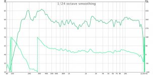
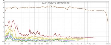
2) Magnitude and phase. The plot had 1/24 octave smoothing and now windowing applied. The peak described above is clear in this response. There's also a hiccup around 2.5 KHz. A resonance? That seems supported by some of the other measurements that follow. Perhaps I should repeat the measurement at other nearfield locations---this one had the mic centered over the diaphragm horizontally and vertically. I should also check other panels and see if they all show it or whether its unique to this one. I'm surprised the phase looks so smooth over mosts of its range. I have the ~1 KHz Bessel low-pass on the midrange and expected to see it mucking around with the phase in that region.
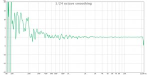
3) Group delay. So I thought maybe something would show up in the group delay but that looks pretty smooth overall and stays below 5 ms over the range this driver is driven, and below 1 ms above 400 Hz (this is still with 1/24 octave smoothing). I was going to try a FIR filter instead of the Bessel filter to avoid phase anomalies but maybe they're not there even with the IIR filter I'm using now.
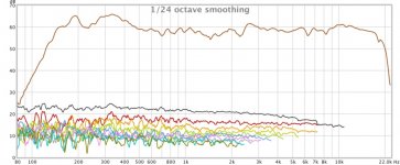
4) Distortion. The panel wasn't driven very hard because the measurement was done nearfield so I won't draw too many conclusions from this graph. It's nice that no screaming distortion peaks point to a terrible buzz somewhere but I'll need to drive things harder before I say much about nonlinear harmonic generation.
5) Waterfall plot of cumulative spectral decay. This was done with a 0.1 ms risetime over a 4 ms window, and 1/48 octave smoothing to retain the details. It doesn't look textbook clean so maybe this points to some refinement opportunities. There are ridges at 2.5 KHz and 5.4 KHz. Resonances? Reflections?
6) Spectrogram. To make the high frequency behavior clearer I applied wavelets rather than Fourier analysis. There's a pretty obvious ridge from a reflection that arrives around 6 ms. To my untrained eye the ridges shown in the waterfall plot don't leap out in this display of the data. Maybe if I play with the range a bit I can pull out some more details.
No doubt someone with more experience with some of these measurements can point out things I've missed or misinterpreted. If so, please chime in. Clearly nearfield measurements don't tell you what happens at the listening seat but I wanted to start here so I could have simpler results to work with in the beginning. I also wanted to see if there are any striking planar magnetic driver misbehaviors I need to know about before getting carried away making frequency response corrections etc.
That said, I should reiterate that all of this was done after equalizing the response I measured at the listening seat (mostly based on the moving mic technique). I could turn that around and see what I get---equalize to optimize the nearfield behavior of the driver and then make a measurement at the listening seat. The line array effects, dipole effects, and room reflections will all conspire against nice behavior at the listening seat, of course, so it would really be more of a self-education exercise than an attempt to achieve a usable set of equalization settings.
Few
...Which provides a segue for this post. I decided to take a closer look at how the planar drivers are behaving. I've been reading up on Room Eq Wizard so this also provides an opportunity to apply some of what I learned. I'm going to post a bunch of nearfield measurements taken with the mic a few cm from the central conductor of one of my planar drivers, grill cloth in place, and with the "crossover" and equalization still applied. Some of these measurements are not super relevant but I'm going to toss them in for completeness. For example, I took a look at distortion just to see if it highlighted any nasty buzzes but since the measurement was done nearfield, the drive level was low and the distortion products are therefore unrealistically low. Nobody has asked for any detail on the design or construction of the DIY planar magnetic drivers so I don't know if these measurement details will be of interest to anyone. I'll throw them into the mix anyway---at least I'll have an easy-access record of my own results.
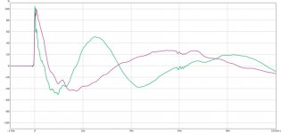
1) Impulse and step response. It looks fairly clean, but the large low frequency oscillation seems to correspond to the ~350 Hz peak seen in the magnitude response, not to the 150 Hz high pass crossover. I'm guessing it's a result of a 5.5 dB Q=2 peak I've added at 345 Hz in the miniDSP equalization. I added that based on measurements at the listening position. What do I conclude from the way it affects the nearfield result? I'll need to figure out a way to determine which works better from the listener's perspective. Maybe listen to pink noise while sitting at the main listening position and alternating between peak and no-peak?
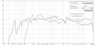
2) Magnitude and phase. The plot had 1/24 octave smoothing and now windowing applied. The peak described above is clear in this response. There's also a hiccup around 2.5 KHz. A resonance? That seems supported by some of the other measurements that follow. Perhaps I should repeat the measurement at other nearfield locations---this one had the mic centered over the diaphragm horizontally and vertically. I should also check other panels and see if they all show it or whether its unique to this one. I'm surprised the phase looks so smooth over mosts of its range. I have the ~1 KHz Bessel low-pass on the midrange and expected to see it mucking around with the phase in that region.
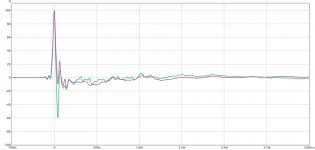
3) Group delay. So I thought maybe something would show up in the group delay but that looks pretty smooth overall and stays below 5 ms over the range this driver is driven, and below 1 ms above 400 Hz (this is still with 1/24 octave smoothing). I was going to try a FIR filter instead of the Bessel filter to avoid phase anomalies but maybe they're not there even with the IIR filter I'm using now.
4) Distortion. The panel wasn't driven very hard because the measurement was done nearfield so I won't draw too many conclusions from this graph. It's nice that no screaming distortion peaks point to a terrible buzz somewhere but I'll need to drive things harder before I say much about nonlinear harmonic generation.
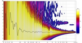
5) Waterfall plot of cumulative spectral decay. This was done with a 0.1 ms risetime over a 4 ms window, and 1/48 octave smoothing to retain the details. It doesn't look textbook clean so maybe this points to some refinement opportunities. There are ridges at 2.5 KHz and 5.4 KHz. Resonances? Reflections?
6) Spectrogram. To make the high frequency behavior clearer I applied wavelets rather than Fourier analysis. There's a pretty obvious ridge from a reflection that arrives around 6 ms. To my untrained eye the ridges shown in the waterfall plot don't leap out in this display of the data. Maybe if I play with the range a bit I can pull out some more details.
No doubt someone with more experience with some of these measurements can point out things I've missed or misinterpreted. If so, please chime in. Clearly nearfield measurements don't tell you what happens at the listening seat but I wanted to start here so I could have simpler results to work with in the beginning. I also wanted to see if there are any striking planar magnetic driver misbehaviors I need to know about before getting carried away making frequency response corrections etc.
That said, I should reiterate that all of this was done after equalizing the response I measured at the listening seat (mostly based on the moving mic technique). I could turn that around and see what I get---equalize to optimize the nearfield behavior of the driver and then make a measurement at the listening seat. The line array effects, dipole effects, and room reflections will all conspire against nice behavior at the listening seat, of course, so it would really be more of a self-education exercise than an attempt to achieve a usable set of equalization settings.
Few
Attachments
-
 nearfield MT impulse MMM eq.jpg57.5 KB · Views: 285
 -
 nearfield MT mag phase MMM eq.jpg78.3 KB · Views: 285
 -
 nearfield MT group delay MMM eq.jpg65.9 KB · Views: 281
 -
 nearfield MT distortion MMM eq.jpg95.5 KB · Views: 283
 -
 nearfield MT CSD waterfall 0.1 ms.jpg112.3 KB · Views: 283
 -
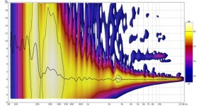 nearfield MT spectrogram wavelet.jpg139.9 KB · Views: 90
Last edited:
Just guessing here from eyeballing the chart, but I suspect your THD is mostly residual measurement noise in the mud. If you played a bit louder, the THD may not go up but the loudness would and so it would measure better.4) Distortion. The panel wasn't driven very hard because the measurement was done nearfield so I won't draw too many conclusions from this graph.
With THD, you know right away when something (the speaker or the mic or the computer) has crossed the line into overload. So you back off a bit.
If not.... the 2% THD indicated isn't quality performance.
Ben
Last edited:
That looks rather flat in the distortion department, I agree with Ben volume might be to low , for sake of distortion you could shove the mic closer, although volume should remain the same and you will see if the problem is the environment?
60 dB on tee scale is prob a bit low , not sure if you calibrated the spl ( I stil did not )
)
60 dB on tee scale is prob a bit low , not sure if you calibrated the spl ( I stil did not
)I removed all equalization except the 50 Hz high pass, increased the stimulus level, and moved the mic 2 mm closer (any closer and it touches the grill cloth). I can repeat with the grill removed but that will be another day.
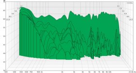
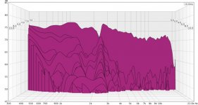
The first three graphs compare results obtained with and without equalization applied (equalized = green, unequalized = purple). The wider bandwidth unequalized results make for nicer impulse and step responses. Removing the 345 Hz equalization peak helps the nearfield step response as well.
The distortion results are now more relevant. 2nd harmonic shows a peak of ~0.2% at 1.2 KHz, 0.6% at 310 Hz, and 1.24% at the 150 Hz crossover frequency I've been using. Looks like I should move that crossover up a bit to rely more on the woofer array at 150 Hz. No sign of a distortion peak at the 2.5 KHz kink in the magnitude response. Perhaps that's a reflection rather than the diaphragm breaking up? The CSD waterfall shows a ridge at that frequency, but again I don't see it in the spectrogram.
Time to turn my attention to my day-job!
Few
Attachments
Oh Aaah I did of know you where already so close mm work I wonder how loud is it is playing, sweeps tend to get on the brink of painfull with a good volume especially mid range/high not really a cyantifific way of loudness but if it like a small breeze you really need to crank it. Then the **** hits the van usually. Better would be using a spl meter , so far it looks pretty good , only the difference beteeen original signal and distortion is rather small but numbers of 0,02 is nothing to be ashamed about I recon not even close to
I wonder how loud is it is playing, sweeps tend to get on the brink of painfull with a good volume especially mid range/high not really a cyantifific way of loudness but if it like a small breeze you really need to crank it. Then the **** hits the van usually. Better would be using a spl meter , so far it looks pretty good , only the difference beteeen original signal and distortion is rather small but numbers of 0,02 is nothing to be ashamed about I recon not even close to- Home
- Loudspeakers
- Planars & Exotics
- DIY planar magnetic + open baffle woofer array