One thing seems astonishing for me.
Your deck is suspended and your arm is not stiffly connected to the platter.
So that there are relative movements between the cartridge and the record.
What Arch is saying is that the suspension of the turntable allows relative motion of the upper plinth, while the arm is fixed on a separate surface. He has a point. As good as the sound that vinuhl says he is getting, there could possibly be huge gains to be made from rigidly coupling the arm to the turntable thereby eliminating that relative movement between the two elements.
Hi super.
The ideal tube/rod size and whether you use a spacer between them is dependent upon the size of bearings used. The important aspect here is the contact angle between the bearing and rod. The shallower the angle the lower the lateral friction will be though too small an angle may result in a carriage that is too easy to inadvertently derail. I reckon an angle of 20degrees is an ideal compromise. With two 6mm tubes touching a 4mm wide bearing is ideal. I am using 4mm rods with a 1.5mm spacer and 4mm wide bearings which gives the 20degree contact. A couple of advantages to this setup are that the rail is shallower so you have a couple of mm more beneath the rods which allows the support structure to be built more rigidly/with more damping material for the same arm geometry. Also the bottom of the V between the rods is flat so dust cannot get stuck in the Sharp angle. As you have a cover over the rail this shouldn't be to much of a problem for you.
I'm in agreement with Colin on the headshell front. Currently you have a really rigid tube connected to quite a thin angle headshell. Also your zenith adjuster is going to add nothing to rigidity. If you want this adjustment just use slightly oversized mounting holes. 2.8mm holes will still allow several degrees of adjustment without compromising mounting solidly. Not only is the block headshell much more rigid it also gives better weight distribution.
In the context of your deck I am not so in agreement with Colin about arm length. The advantage of a longer arm is is ability to deal with warps. As you have excellent clamping warps aren't going to be a problem for you. Shorter arm tubes have two advantages. Rigidity and all the advantages this gives. Also lateral tracking. The two bearings and the stylus form a triangle with the stylus at the peek. The shallower the angle of this peek the better. As the stylus tries to push the carriage against the bearings friction a torsional element is created. Halve the length of the arm and you halve the torsion. Increasing the distance between the bearings also reduces this torsion. I think increasing the spacing between your bearings will improve your carriage. Ideally you want all of the force from the stylus to only push the bearings laterally with no torsion. Alhough in practice this is not possible reducing the effect as much as possible is desirable.
I had spotted the suspended deck/unsuspended arm point and was wondering what your plans on this front were. Normally with an arm like yours I would expect to see a diy deck built specifically to fit it being planned. As you have a top notch deck already what are your plans?
Niffy
Still Building
Hi All.
I seem to have resolved my skipping problem, fingers crossed. I washed out my bearings but also noticed that I had a small bit of gak stuck to my stylus. I had been suffering a slightly recessed midrange which I had atributed to excess bearing friction but was probably the dirty stylus. All is singing sweetly now.
What with the tracking problem and a percistant head cold I haven't had time to cosmetically finish the sub-chassis as hoped. As I had the deck out of its cabinet for bearing cleaning I took some pictures of it as it is.


The photos don't really do it justice. At the moment the deck is being used as medium mass solid plinth deck. The suspension and main plinth are to follow, hopefully soon. One unforseen bonus to the look of the deck is wife approval. My wife is not a fan of the appearance of most hi-fi so I've had to compromise on a lot of my projects. Luckly she loves the look of this deck and has INSISTED that I get it out of the cabinet and build a dedicated stand for it. Yipee. I wonder if I can bring her round to the idea of some electrostatics. Wishfull thinking.
Niffy
Hi All.
I seem to have resolved my skipping problem, fingers crossed. I washed out my bearings but also noticed that I had a small bit of gak stuck to my stylus. I had been suffering a slightly recessed midrange which I had atributed to excess bearing friction but was probably the dirty stylus. All is singing sweetly now.
What with the tracking problem and a percistant head cold I haven't had time to cosmetically finish the sub-chassis as hoped. As I had the deck out of its cabinet for bearing cleaning I took some pictures of it as it is.
The photos don't really do it justice. At the moment the deck is being used as medium mass solid plinth deck. The suspension and main plinth are to follow, hopefully soon. One unforseen bonus to the look of the deck is wife approval. My wife is not a fan of the appearance of most hi-fi so I've had to compromise on a lot of my projects. Luckly she loves the look of this deck and has INSISTED that I get it out of the cabinet and build a dedicated stand for it. Yipee. I wonder if I can bring her round to the idea of some electrostatics. Wishfull thinking.
Niffy
One thing seems astonishing for me.
Your deck is suspended and your arm is not stiffly connected to the platter.
So that there are relative movements between the cartridge and the record.
Good point. I knew that. But in my case, it is almost impossible to mount the arm on SME table. Its suspension is not strong enough to hold the arm. And I don’t want to modify the SME table. I thought to use my office table, which is a VPI Scout. So both arm and table can be on a rigid surface. But Scout is not as good as SME. Or I can take the suspension off. They are basically some rubber bands. The table and arm will be both on a rigid surface.
Last edited:
Hi All.
I seem to have resolved my skipping problem, fingers crossed. I washed out my bearings but also noticed that I had a small bit of gak stuck to my stylus. I had been suffering a slightly recessed midrange which I had atributed to excess bearing friction but was probably the dirty stylus. All is singing sweetly now.
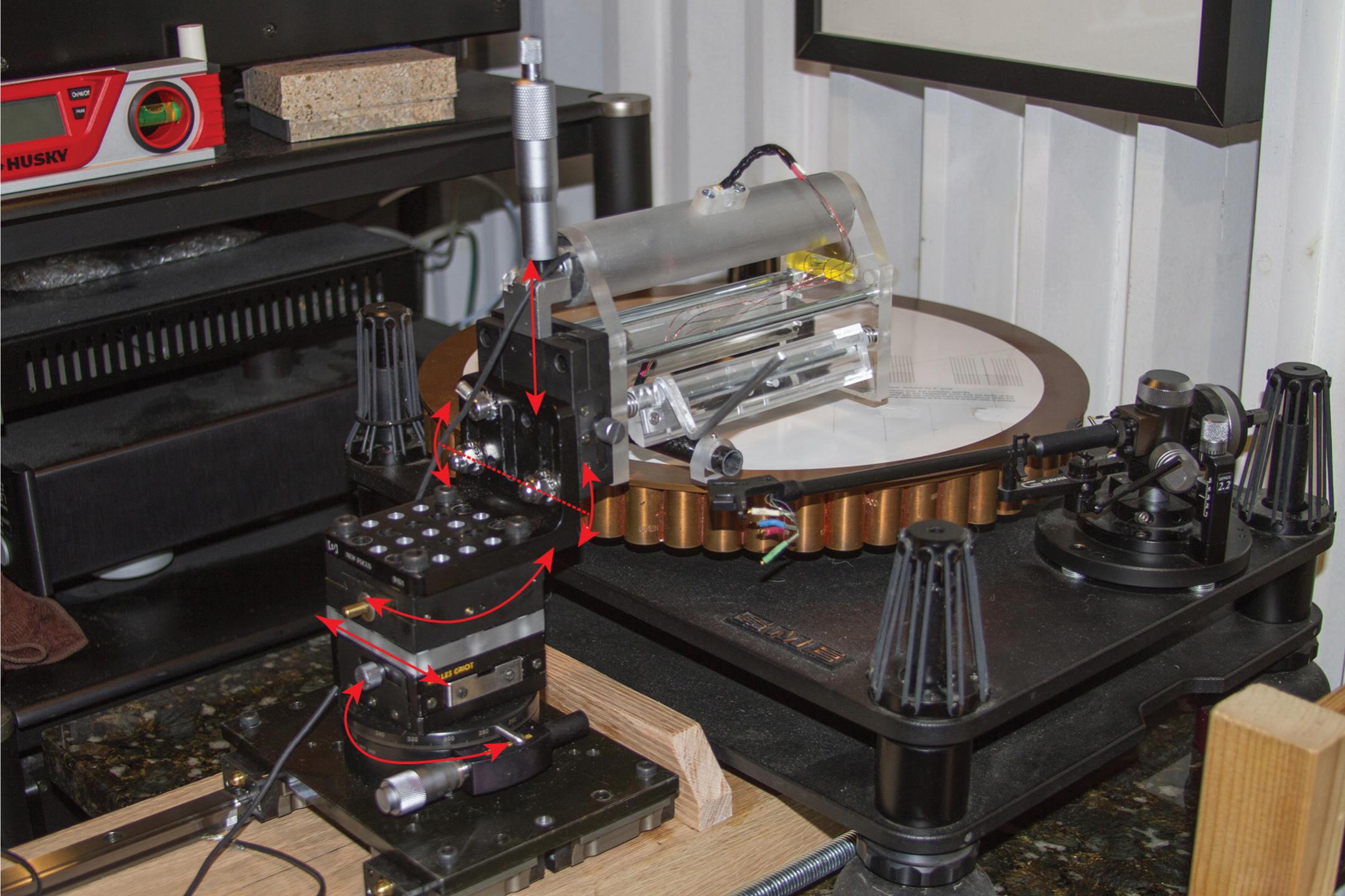
What with the tracking problem and a percistant head cold I haven't had time to cosmetically finish the sub-chassis as hoped. As I had the deck out of its cabinet for bearing cleaning I took some pictures of it as it is.
View attachment 427605
View attachment 427606
View attachment 427607
The photos don't really do it justice. At the moment the deck is being used as medium mass solid plinth deck. The suspension and main plinth are to follow, hopefully soon. One unforseen bonus to the look of the deck is wife approval. My wife is not a fan of the appearance of most hi-fi so I've had to compromise on a lot of my projects. Luckly she loves the look of this deck and has INSISTED that I get it out of the cabinet and build a dedicated stand for it. Yipee. I wonder if I can bring her round to the idea of some electrostatics. Wishfull thinking.
Niffy
Beautiful work!
Niffy,
As always, awesome work!, that is a beautiful piece!
Super,
I didn't realize that was a suspended plinth, that explains the micro detail issues. The more rigid between the platter bearing and arm I had made this design the better the detail became, the nature of the design makes it even more rigid than the Clearaudio and Cantus so it benefits from being locked well to the turntable.
Colin
I made a plan to build a suspended platform. It integrates top plinth of SME table as one suspended platform and leaves the bottom plinth of SME as is. Therefore, I can place the heavy arm base and platter on the same suspended platform. What do you guys think if suspended platform is good for this kind of arm or not?
Thanks all.
Super.
What ever you build it's going to have to be very big to accommodate the slide rails of you arm. My thoughts on a possible deck is to build a massive solid plinth. I would loose both plinth sections from the SME and just use the platter, bearing and motor. The plinth would need to be stepped to accommodate the hight difference. Maybe thick acrylic sandwiched between aluminium, if funds allow. Add weights to the plinth so that the centre of mass of the deck coincides with the centre of the plinth. Then sit the whole thing on a motorcycle inner-tube. The suspension can be tuned buy adjusting the pressure in the tube and levelled by moving the weights. I've used a similar system, an inner-tube between two paving slabs, under turntables, amplifiers and cd players with great success.
Niffy
For all,
Here's a little test, it's quick and simple and you need a test record to do it wih a frequency sweep. I was working on a new wand with a flat 1/8" Alu headshell but abandoned it. Why?, because of a clear resonant node in the. 2k -5k region, the Alu upright block with less contact area doesn't have a node in this area, in fact it seems to be above 10k. This test must be done with no amplification and will clearly show where the anomalies rest.
Colin
Thanks all.
Super.
What ever you build it's going to have to be very big to accommodate the slide rails of you arm. My thoughts on a possible deck is to build a massive solid plinth. I would loose both plinth sections from the SME and just use the platter, bearing and motor. The plinth would need to be stepped to accommodate the hight difference. Maybe thick acrylic sandwiched between aluminium, if funds allow. Add weights to the plinth so that the centre of mass of the deck coincides with the centre of the plinth. Then sit the whole thing on a motorcycle inner-tube. The suspension can be tuned buy adjusting the pressure in the tube and levelled by moving the weights. I've used a similar system, an inner-tube between two paving slabs, under turntables, amplifiers and cd players with great success.
Niffy
Niffy,
Thank you for your suggestions! After carefully thinking, I decided to just loose the suspensions on the SME turntable. It is simple to do so I can get the arm done first. Both the arm and the table are on same solid ground now. I also took the Graham arm off the table. I thought I could use both Graham and the diy arm at same time and switch arms around. But in order to do so, I had to work within very tight space. Now I have a lot of space to do what I want. However, I may go back to suspended table later on.
For all,
Here's a little test, it's quick and simple and you need a test record to do it wih a frequency sweep. I was working on a new wand with a flat 1/8" Alu headshell but abandoned it. Why?, because of a clear resonant node in the. 2k -5k region, the Alu upright block with less contact area doesn't have a node in this area, in fact it seems to be above 10k. This test must be done with no amplification and will clearly show where the anomalies rest.
Colin
Hi Colin.
I'm intrigued as to what this simple test could be. Please share. What is the procedure, are any items other than the aforementioned test record needed and how do you interpret the results. Not getting any resonance nodes below 10khz is an astounding result. This should give your arm near perfect neutrality. Impressive work.
Niffy
Hi Niffy,
If I'm correct a high frequency resonance will be excited by a tone which falls in its resonant zone. If the arm has a resonant frequency of say 5khz a frequency sweep of a test record should make this tone most audible and and amplified by the arm itself with no volume at 5k. It will be heard as a peak in the sweep mechanically. I found this peak around 12k, at which my arm was excited into audible resonance.
If I'm correct a high frequency resonance will be excited by a tone which falls in its resonant zone. If the arm has a resonant frequency of say 5khz a frequency sweep of a test record should make this tone most audible and and amplified by the arm itself with no volume at 5k. It will be heard as a peak in the sweep mechanically. I found this peak around 12k, at which my arm was excited into audible resonance.
Thanks Colin.
If 12khz represents the fundamental of your arm then all of its harmonic nodes will present outside of the audio bandwidth. This is very close to what I was trying to achieve in the design of my carriage though I was aiming to push the fundamental out of the audio band as well. I managed to push the fundamental to 19khz which is outside of my personal audio bandwidth. However I did achieve this at the expense of carriage mass which in itself is not a problem and in terms of lateral effective mass beneficial. My higher mass does mean that I suffer proportionately higher bearing friction and therefore reduction in cantilever tangential alignment. Although the sound quality I have achieved with my arm is stunning it would be remiss of me not to pursue all possible avenues of possible improvement. Would the improved cantilever alignment of a lower mass carriage outweigh the higher resonant frequency of my current model? I thought not. However if your test does represent the actual fundamental of your arm then very possibly it would. I had assumed your arm to have a fundamental of about 4khz.
I think I need to build a lighter carriage and find out for sure.
Niffy
I am about to try a two tube version using twin 6mm tubes. My bearings IIRC are 10x5x5mm. I am wondering the distance between the bearing and the T brace... how long should the axles for the roller bearings be? I've some plastic pieces that snug fit into the inside of the bearing and just need to cut to length and fit to my T. Thanks.
Hi Mortron,
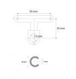
I am working on my 2nd version of arm now. Please see attached image for the dimensions. I use a 7 mm spacer for the bearings.
I think I find a way to make same kind of glass track as Clear Audio’s now. See the image. And, I will try it out in two weeks. If it works, I think it is definitely better than twin glass tubings.
Attachments
Hi Mortron,
I am working on my 2nd version of arm now. Please see attached image for the dimensions. I use a 7 mm spacer for the bearings.
I think I find a way to make same kind of glass track as Clear Audio’s now. See the image. And, I will try it out in two weeks. If it works, I think it is definitely better than twin glass tubings.
Hi super.
The 50mm spacing between bearings should definitely help lateral tracking. I think the drop of 30mm might be a bit excessive. The arm tube only needs to just clear the bottom of the track tube. Your current design will put the pivot about 40mm above the record surface. Combined with your sub-50mm arm length warp wow may prove an issue even though you have excellent record clamping. Although having the COM below the pivot is good for stability having it too low can have 2 negative effects. Eccess tracking force variations on warps, though in your case probably not a major problem. As everything is further from the pivot vertical effective mass will be dramatically increased. You could easily have a vertical effective mass of 30grams.
I think the two rail version (thanks PDR) is probably superior to running inside of a tube as movement other than lateral is prohibited. It would be much easier to twist the carriage laterally as the bearings can slide up the inside of the tube different amounts. As the load inevitably has a torsional element this is likely to occur. With the 2 rod design it cannot.
Hope this helps.
Niffy
- Home
- Source & Line
- Analogue Source
- DIY linear tonearm