I like two balls idea as well. If I do, I will do the following.
1. Don’t use 90 degree angles as rail. I will use 120 degree angles and glue glass bars on the contact sides of rails.
2. Use two ceramic balls. Not steel balls.
Hi Super,
Welcome to my camp. This looks like the latest evolution of my original work with window glass tracks. I think you are correct on both your counts above. I've been thinking on those lines also. Here are a couple of suggestions which may be useful. Use window glass for quick and easy tests. I've been researching borosilicate flat glass and found it is available. Try Google-ing borosilicate float glass. Get some of that asap. Next reduce the overall weight of the carriage by eliminating the metal angle support of whatever you choose for an angle. 120 degrees sounds about right. My earlier work with glass trax tended to show little if any difference in performance with different angles. This may not really be the case. Ceramic balls should have the advantage in terms of being rust free and you can choose a diameter to provide the correct spacing between the rails. Keep us posted please.
BillG
Hi BillG,
I think ceramic balls are not only rust free but also have less friction than steel balls.
Balls Ceramic Silicon Nitride (Si3N4) Series
They are cheap and come with different sizes.
Jim
I think ceramic balls are not only rust free but also have less friction than steel balls.
Balls Ceramic Silicon Nitride (Si3N4) Series
They are cheap and come with different sizes.
Jim
Hi Niffy,
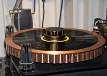
Here is the detail information about my outer ring. I also found some of old pictures of the ring.
I bought the ring from TTWeight audio when they just started business years ago. They only made outer rings and all the outer ring they made had no weights at that time. But their ring is not easy to use and is too light. So, I decided to modify the ring.
TTW Outer Record Rings
I think they call the ring I bought classical now.
My ring consists of two parts.
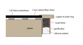
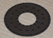
One part is the record mat. I bought the mat from TT Weights as well. The mat is made of 1 mm carbon fiber sheet. I think 2 mm is better. On the back of the carbon fiber mat, I stick small pieces of sorbothane. I cut them from a 1/8” sheet.
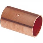
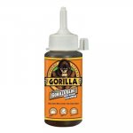
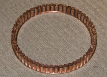
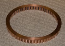
The other part of the outer ring is the ring itself. I glued 56 pieces of copper cups( for plumbing) around the ring on the bottom. They made almost perfect fit. There are about 2 mm space left between last two cups. So, once I put the ring on platter, the ring is centered. I filled these cups with same amount of lead shots by weight. The lead shots filled about half of the cups. Then, I poured Gorilla glue into these cups. Gorilla glue expends once it is dry. It fills all small space between lead shots. Finally, I sealed these cups with silicone sealant. In one of the pictures, you can see the lead shots with Gorilla glue, I didn’t seal the cups with silicone yet when the picture was taken.
The outer ring helps needle to track the information in groove accurately.
Here is the detail information about my outer ring. I also found some of old pictures of the ring.
I bought the ring from TTWeight audio when they just started business years ago. They only made outer rings and all the outer ring they made had no weights at that time. But their ring is not easy to use and is too light. So, I decided to modify the ring.
TTW Outer Record Rings
I think they call the ring I bought classical now.
My ring consists of two parts.
One part is the record mat. I bought the mat from TT Weights as well. The mat is made of 1 mm carbon fiber sheet. I think 2 mm is better. On the back of the carbon fiber mat, I stick small pieces of sorbothane. I cut them from a 1/8” sheet.
The other part of the outer ring is the ring itself. I glued 56 pieces of copper cups( for plumbing) around the ring on the bottom. They made almost perfect fit. There are about 2 mm space left between last two cups. So, once I put the ring on platter, the ring is centered. I filled these cups with same amount of lead shots by weight. The lead shots filled about half of the cups. Then, I poured Gorilla glue into these cups. Gorilla glue expends once it is dry. It fills all small space between lead shots. Finally, I sealed these cups with silicone sealant. In one of the pictures, you can see the lead shots with Gorilla glue, I didn’t seal the cups with silicone yet when the picture was taken.
The outer ring helps needle to track the information in groove accurately.
Attachments
-
 001-1.jpg27.8 KB · Views: 728
 -
 outer-ring-construction.jpg51.3 KB · Views: 316
 -
 a492305b-3cbc-4fda-baef-a647085eeabb_400.jpg14.2 KB · Views: 177
 -
 42a75d81-f5d4-45c3-8adc-3518cecfebe9_400.jpg12.2 KB · Views: 252
 -
 006-1.jpg32.3 KB · Views: 665
 -
 004-1.jpg28.2 KB · Views: 709
 -
 003.jpg50.1 KB · Views: 721
 -
 002-1.jpg32.2 KB · Views: 726
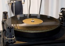
Forgot to mention that the total weight of the outer ring is 6 lbs and 8 ozs. 6 lbs is on the heavy side. I think 4 lbs should be enough in most of cases. SME's motor does have enough power to drive the platter with the outer ring. I measured wow and flutter with the outer ring and without the outer ring. I couldn't see significant difference so I think the weight of the outer ring is ok.
Hi Super.
Nice work. 6lb will definitely flatten even the most severe warps especially when combined with the grip and pull SME central clamp. With the way SME build things I doubt the main bearing even notices the extra mass.
I'll be busy over the next couple of days but will try and share the spread sheet soon. I used open office for the spread sheet which isn't anywhere near as compatable with excel as Sun claims. I'll do my best to make it make sense.
Niffy
Pardon me for some distractions! ")
Someone mentioned rigidity of the horizontal bar and this Polish tonearm seems to be pretty rigid. I like its simplicity and certainly simpler than the Clearaudio TT1. I also like the armwand can be detached from the acrylic ring by unlocking the set screws and it might be able to adjust VTA from that too. Pretty neat.
Too bad there's no picture of its bearing assembly. I think it's just another variation of a Cantus concept.
Here's also a YouTube video showing the arm in action:
Ok, please go back to your regular program!
.
Someone mentioned rigidity of the horizontal bar and this Polish tonearm seems to be pretty rigid. I like its simplicity and certainly simpler than the Clearaudio TT1. I also like the armwand can be detached from the acrylic ring by unlocking the set screws and it might be able to adjust VTA from that too. Pretty neat.
Too bad there's no picture of its bearing assembly. I think it's just another variation of a Cantus concept.
Here's also a YouTube video showing the arm in action:
An externally hosted image should be here but it was not working when we last tested it.
An externally hosted image should be here but it was not working when we last tested it.
An externally hosted image should be here but it was not working when we last tested it.
An externally hosted image should be here but it was not working when we last tested it.
An externally hosted image should be here but it was not working when we last tested it.
An externally hosted image should be here but it was not working when we last tested it.
An externally hosted image should be here but it was not working when we last tested it.
Ok, please go back to your regular program!
.
Last edited:
New and improved wand and counterweight.
And headshell?
Niffy,
Yes headshell too. Same mass as previous but wider contact point at the bottom. The lower profile headshell and counterweight design makes it incredibly stable. The counterweight is also polycarbonate /aluminum hybrid for decoupling. All worked out by testing the wand and counterweight balanced upon a. 1/2" flat edge, twisting and watching how quick it settles rather than rocking side to side.
This quality is a dramatic improvement in the bass since all lower bass modulation is lateral. I've noticed in this design if the mass is all primarily below the wand this loads the bearings and increased mass has little to no effect on the cantilever.
Colin
Yes headshell too
. Same mass as previous but wider contact point at the bottom. The lower profile headshell and counterweight design makes it incredibly stable. The counterweight is also polycarbonate /aluminum hybrid for decoupling. All worked out by testing the wand and counterweight balanced upon a. 1/2" flat edge, twisting and watching how quick it settles rather than rocking side to side. This quality is a dramatic improvement in the bass since all lower bass modulation is lateral. I've noticed in this design if the mass is all primarily below the wand this loads the bearings and increased mass has little to no effect on the cantilever.
Colin
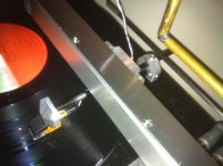
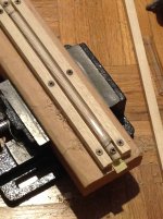
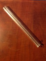
Ok, I did C shape glass tubing.
I made a attachment to hold the tubing and used a grinder first. Then, I used a cordless drill and small grinding wheels to do the detail, and finished it with knife sharpening stone with water. It took a lot of patient and time to get it done. The first one was cracked because I put too much pressure on it. It is not the most beautiful thing in the world, but it works.
I decide to have 2nd try and perfect it. I ordered some tools and decided to change 11mm ID tubing to 10mm ID tubing to give it even tighter fit.
Attachments
Last edited:
Hi Super.
Much earlier in this thread someone posted a video link showing a homemade glass tube cutter. It was fast and gave a good clean cut. It was for cutting the tube to length but the idea could be adapted to cut along the length to make a slot. The key to the success of this cutting rig was using a high speed dremil type drill with a diamond cutting disk with a constant stream of water to cool and lubricate.
Niffy
from what I understand these kind of tubes can be easily cut with a standard hardware store glass cutter the type used for window glass. seems a simple step to make the above style jig which would provide two spaced guide edges for a glass cutter to run along spaced to provide the desired gap. Worth a try. Best regards Moray James.
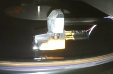
Shot from side of headshell
Hi Colin.
How is the headshell attached to the arm tube?
Niffy.
He Colin you don't need to cut your carbon tube to take the assembly apart. soak the adhesive joint in Acetone to dissolve the instant glue. If that is not getting at all the adhesive then heat the assembly in the oven 325 to 350F should do and you can try the solvent a second time it you need to. This may save you cutting expensive tubes. Hope this helps. Best regards Moray James.
PS: very nice work by the way.
PS: very nice work by the way.
Shot from side of headshell
Are those machine screws steel? If so you should try swapping them out for Titanium or top quality Stainless which will both be more or less non magnetic. Makes a difference. Best regards Moray James.
- Home
- Source & Line
- Analogue Source
- DIY linear tonearm