OK, so I'm feeling a little nutty. Now we are in the really low distortion region. Input pair is the same as the other circuit, but this one has the buffer as well. This is pretty freaking low distortion if you ask me!
Thanks for the ideas!
Thanks for the ideas!
Attachments
Oops, now I have a resonance at some 5MHz or so... shoot!
Could you post a current schematic each time, unobscured by the sim readout? Or at least label them as to rev level and refer to the number or letter. We are, I suspect, understandably losing our place.
Also, Bonsai, who makes good points where I can understand them, I believe should step up to the plate and show us his (or her) preferred topology, despite it not being accessible within the tearup constraints. No salesman will call
Brad
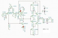
OK, this is the first version with double darlingtons in the input stage, and a darlington in the VAS. Distortion was as before, but resonance remains. I call this "Simple Line Stage DD v.1.0". There's a resonance peak at about 12MHz. I tried killing it with the Miller capacitor but it's gets so large that the slew rate probably suffers.
Attachments
Try to put a cap over R10.
Fortunately, this time it's effective. In previous versions of this circuit, that cap wasn't useful. I know this is the normal thing to do, but it was performing very well before without one. So, I put 47pF across R10 and it's fine now. Thanks.
Distortion is back up @ 0.007%. Capacitors are evil....
Last edited:
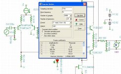
OK, someone suggested adding a capacitor between the output of the VAS and the feedback network. So, I did this. I added the 220pF between the Miller capacitor and the feedback network. This makes for a nice smooth roll off (with a very small bump) at about 2MHz, and the bonus is that distortion is actually lower! It is now 2.2x10^-5 (0.000022% I think). I can have the roll off I need as well as the low distortion I want!
Attachments
OK, someone suggested adding a capacitor between the output of the VAS and the feedback network. So, I did this. I added the 220pF between the Miller capacitor and the feedback network. This makes for a nice smooth roll off (with a very small bump) at about 2MHz, and the bonus is that distortion is actually lower! It is now 2.2x10^-5 (0.000022% I think). I can have the roll off I need as well as the low distortion I want!
Attempts to close the loop that way are frequently found to entail high frequency oscillations, at least in power amplifiers (see Self's article in Linear Audio Vol. 0 for example, "Inclusive Compensation and Ultra-low Distortion Power Amplifiers"). Self shows a way of doing it partway without typically having difficulties. However, the motivation is usually reduction in output-stage distortion, and your output stage is pretty free from the need for that. So maybe it's worth doing for other reasons.
I think it's getting to be time for you to heat up the soldering iron and get your feet wet. Wait, maybe that's a little too mixed of a metaphor
PS: My guess is that "beta enhancement" probably just refers to the insertion of an emitter follower between the diff output and the "VAS" input base, which as Godfrey pointed out is not identical to using a darlington --- you want to ensure some emitter current that's a good deal more than the "VAS" base current, and avoid the voltage modulation of the new device's collector-base capacitance and the attendant distortion.
Attempts to close the loop that way are frequently found to entail high frequency oscillations, at least in power amplifiers (see Self's article in Linear Audio Vol. 0 for example, "Inclusive Compensation and Ultra-low Distortion Power Amplifiers"). Self shows a way of doing it partway without typically having difficulties. However, the motivation is usually reduction in output-stage distortion, and your output stage is pretty free from the need for that. So maybe it's worth doing for other reasons.
I think it's getting to be time for you to heat up the soldering iron and get your feet wet. Wait, maybe that's a little too mixed of a metaphor
Thanks. I have no idea why that capacitor works, at least in simulation. It was just a "let's see what this does" kind of thing.
Unfortunately, I don't have the means to test a circuit like this in the real world, so I have to just trust the sim for now. I'm working on getting some of the MPSA77's, since they are "on order" at Mouser. Fairchild is discontinuing them. There seems to be very few PNP darlington transistors in the TO-92 package.
PS: My guess is that "beta enhancement" probably just refers to the insertion of an emitter follower between the diff output and the "VAS" input base, which as Godfrey pointed out is not identical to using a darlington --- you want to ensure some emitter current that's a good deal more than the "VAS" base current, and avoid the voltage modulation of the new device's collector-base capacitance and the attendant distortion.
Here's a page on this by Mr. Self:
Distortion In Power Amplifiers
It's section 5.2.2. You're right, there's no darlington in there, just either cascoding or an extra emitter follower.
Thanks. I have no idea why that capacitor works, at least in simulation. It was just a "let's see what this does" kind of thing.
Unfortunately, I don't have the means to test a circuit like this in the real world, so I have to just trust the sim for now. I'm working on getting some of the MPSA77's, since they are "on order" at Mouser. Fairchild is discontinuing them. There seems to be very few PNP darlington transistors in the TO-92 package.
Well then, as you continue to live in Simland, it may be time to start simulating the circuit's response to fast square waves, as you have just added a whole lot more work for the available diff pair current in changing the output voltage.
Do you at least have an oscilloscope?
Well then, as you continue to live in Simland, it may be time to start simulating the circuit's response to fast square waves, as you have just added a whole lot more work for the available diff pair current in changing the output voltage.
Do you at least have an oscilloscope?
Yeah, I just bought an old scope. I used to have a whole basement full of old test gear, but that was 20 years ago when I was wading in vacuum tubes.
There's no noise figure listed for the MPSA77, do I assume it's noisy then?
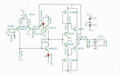
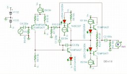
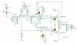
Working on this thing is addictive. I simplified the buffer. It's now a simple push pull darlington arrangement, but I don't think the MPSA77 and MPSA27 are compliments of each other. Anyway, distortion is 2x10^-5%, bandwidth rolls off as before with that funny 220pF capacitor in place.
Attachments
Yeah, I just bought an old scope. I used to have a whole basement full of old test gear, but that was 20 years ago when I was wading in vacuum tubes.
There's no noise figure listed for the MPSA77, do I assume it's noisy then?
Excellent! So you will likely be able to see oscillations and other details.
Darlingtons used to be popular for use in relatively high impedance circuits, particularly when JFETs were ~experimental, since the base current and associated noise in that current is small. For your applications they are of questionable advantage in the input stage (since your input impedance and feedback divider impedances are fairly low), and help a bit in the second stage at low frequencies (although the arrangement advocated by Godfrey and shown by Self will be higher performance).
The effect of having two transistors in the Darlington connection on voltage noise is deleterious, as the voltage noise generators are in series and although uncorrelated add in r.m.s. fashion. Moreover the input device operates at no more than the base current of the second device, and this makes its voltage noise highish (there must be a wiki about noise in bipolars, but the essence is one has at least the "half-thermal" noise of the equivalent internal emitter resistance, i.e. the reciprocal of the transconductance --- and as transconductance goes up with emitter current, voltage noise falls, until the thermal noise in the internal base resistance rbb' becomes the more important term). The takeway about bipolars is that they have an optimum bias point for noise given the source impedance: too high and parallel ("current") noise dominates, too low and voltage noise dominates. When the source impedance is low you can tolerate a rich quiescent current.
But having blabbed all of that, you are dealing with a line-level amplifier, and probably have noise in your signal source and (even with the lower Z now) thermal noise in your feedback network that will exceed that of this diff stage, so as a practical consideration it's probably not too serious.
So in my estimation: no advantage for Darlingtons in the diff pair (but no great disadvantage except making things a little slower, mostly) and some possible advantage in the second stage (including raising the input voltage another ~550mV and allowing the input resistor to be a little larger). And as you remarked, PNP integrated Darlingtons are an endangered species. I suspect the principal application of integrated Darlingtons in audio is for Vbe multipliers used for temperature compensation of power amp output stages, and there an NPN works as well as a PNP.
Working on this thing is addictive. I simplified the buffer. It's now a simple push pull darlington arrangement, but I don't think the MPSA77 and MPSA27 are compliments of each other. Anyway, distortion is 2x10^-5%, bandwidth rolls off as before with that funny 220pF capacitor in place.
Actually that's not too bad an idea, although what the sim will probably not tell you is that the standard red LEDs have a tempco of forward voltage about the same as a single bipolar's base-emitter voltage, and the Darlingtons have more than twice this (the tempco is a weak function of collector current density, rising at low currents). The diamond buffer is better temperature-compensated (although PNPs are usually not a perfect match to NPNs). However, with the 47 ohms in each emitter you're probably fine in domestic environments.
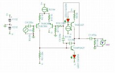
Nice! You can save a couple of parts by biasing the LEDs with the VAS current, instead of dedicated CCSs (See untidy pic below).I simplified the buffer. It's now a simple push pull darlington arrangement...
I share bcarso's lack of enthusiasm for Darlingtons though, and would probably use a single LED with the BC327/BC337 pair (or similar) and 22R emitter resistors.
I don't think that's a big deal here in a class A stage with a few hundred mV across the emitter resistors. A temperature change of 20 degrees centigrade only changes the idling current by 10% or so (rough thumb-suck)....tempco...
Attachments
Oh OK, so they're not too bad then. Why not use one to load the VAS as well? That would free up some valuable board space. You could probably even include a simple output buffer on the original PCB. Something like in the circuit below.The CRD's have internal impedances of 1M ohm....
CRD's fit on the board much better than discrete components....
BTW, don't get trapped into thinking you have to add more parts to improve something. Often simpler is better. A couple of examples that come to mind, from the masters of high end audio design:
Nelson Pass's F5 power amp contains a grand total of 4 transistors in the signal path (plus 2 in the protection circuitry).
The CTC Blowtorch preamp, widely regarded as one of the best in the world, has no output buffer.
Attachments
Last edited:
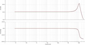
This is an updated version with no buffer. Distortion is 0.0009% into 10kohms @ 1kHz, 1Vp-p. I changed the input differential back to the BC560, adjusted the load resistor, and increased the current in the VAS. Bandwidth has a nice smooth roll off above 1MHz. This version is very simple, with just the 220pF capacitor needing to be added to the board. Everything else has a hole or some kind of landing spot.
Attachments
Last edited:
- Status
- This old topic is closed. If you want to reopen this topic, contact a moderator using the "Report Post" button.
- Home
- Source & Line
- Analog Line Level
- discrete op amp