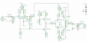
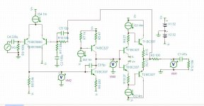
Here's the latest version. I figured out that I needed to delete one capacitor, add another and an inductor. I found the signal analyzer in Tina and saw that I'd made a radio oscillator! So, the response is much better tamed now, but the distortion is up. That 8pF capacitor around the 33k feedback resistor adds a lot of distortion. I mean, take that thing out and the distortion goes way down, by 5 or more times less. I don't know how else to tame the RF response. The inductor was necessary because the amplifier peaks at something like 7MHz and the inductor blocks the input at those frequencies. The Miller integration capacitor did not help to shape the HF response, which I thought was strange.
Attachments
It's not just about distortion. To work properly, there has to be a fixed voltage between the base of T4 and the positive supply line (not ground). To see the problem with your existing circuit, try changing the positive supply voltage by just 1Volt. Current through T4 and T3 should change quite dramatically. Alternatively, try adding some ripple voltage to the supply rail, and see what you get at the output.Swapping the current source and resistor in the bias network for T4 made the distortion worse as well (0.0033% vs 0.0011%). The alternate arrangement was 910 ohms on top with 1ma below.
Now you're catching on. Poof - C3 is gone at last!...and saw that I'd made a radio oscillator!

The inductor's a bad idea though; it's just hiding the problem, not fixing it. That peak a 7MHz means it's still very close to oscillating. A suitable Miller cap should be able to tame it, maybe with a bit of help from a small cap across the feedback resistor. Reducing or removing the resistor between T4 and the diamond may help too.
It's not just about distortion. To work properly, there has to be a fixed voltage between the base of T4 and the positive supply line (not ground). To see the problem with your existing circuit, try changing the positive supply voltage by just 1Volt. Current through T4 and T3 should change quite dramatically. Alternatively, try adding some ripple voltage to the supply rail, and see what you get at the output.
Actually, the constant voltage was between the base of T4 and the V- supply, but I changed it as you suggested.
Now you're catching on. Poof - C3 is gone at last!
The inductor's a bad idea though; it's just hiding the problem, not fixing it. That peak a 7MHz means it's still very close to oscillating. A suitable Miller cap should be able to tame it, maybe with a bit of help from a small cap across the feedback resistor. Reducing or removing the resistor between T4 and the diamond may help too.
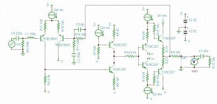
The peak was from a resonance at T4, the voltage gain transistor. I had to make the Miller capacitor huge to tame it. It's now 220pF. Thanks!
Attachments
Here's the latest schematic. Distortion is now 0.0056% (500mV peak-to-peak, 1kHz, 10kohm load). It doesn't change much with input level, but changes a lot with frequency. I have the Fourier analyzer set to 10 harmonics. I don't think I can make this any better.
Thanks again everyone for your kind suggestions.
Thanks again everyone for your kind suggestions.
Attachments

You can always cram more stuff on the PCB if you do it deadbug style. i.e. Glue the transistors upside-down on the board with their legs sticking up in the air, then solder all the other components to them and each other and the PCB as appropriate.I can't easily add a current mirror or any other transistors to this circuit since at that point I might as well perfboard the entire thing.
 Erm, OK, that didn't sound good. TBH, it looks even worse, but it does work well. Seriously. There's a nice example here: QRP HF LINEAR AMPLIFIER by Harry Lythall
That said, it wouldn't hurt to simplify things. Do you really need a diamond buffer in the output? It's not like it's driving headphones or speakers. A simpler output stage would save about half a dozen components.
Oopsie, there goes the slew rate (down to about 2V/uS). If you increase R17 and R18, then you can use a smaller Miller cap. 470 Ohms or so each, maybe more. Doing that reduces the gain of the input stage, but improves it's linearity. It may also be a good idea to leave out R6 (and adjust R8 as needed) - it's killing the current gain of the VAS.I had to make the Miller capacitor huge to tame it. It's now 220pF.
You can always cram more stuff on the PCB if you do it deadbug style. i.e. Glue the transistors upside-down on the board with their legs sticking up in the air, then solder all the other components to them and each other and the PCB as appropriate.
That said, it wouldn't hurt to simplify things. Do you really need a diamond buffer in the output? It's not like it's driving headphones or speakers. A simpler output stage would save about half a dozen components.
Oh my God, that looks really scary!
Thanks for sharing! Well, earlier in this thread many people said that this circuit couldn't drive a grain of sand down a mountain, or words to that effect, so I got concerned and looked around for a solution. I have a basic push pull output stage I can use instead of the diamond buffer. I need something to drive two single ended outputs with something like 20kohms input impedance each. The cable may be a couple of meters long, but I'm not sure about that yet. I'm aware that the VAS stage appears to be very sensitive to load, which is why I believe the coupling resistor I had in there between it and the buffer reduced distortion. The buffer doesn't have a huge input impedance apparently, though I have not calculated that yet.
Thanks again for your kind assistance. This is the first time I've ventured into designing with transistors. I come from the tube world from a long time ago and I never really "got" bipolar transistors until recently. I'm still not sure I understand them completely, but I sure do understand them a lot more now.
Oopsie, there goes the slew rate (down to about 2V/uS). If you increase R17 and R18, then you can use a smaller Miller cap. 470 Ohms or so each, maybe more. Doing that reduces the gain of the input stage, but improves it's linearity. It may also be a good idea to leave out R6 (and adjust R8 as needed) - it's killing the current gain of the VAS.
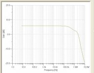
Huh. OK. The frequency response is nice and flat out to beyond 100kHz, then rolls off very nicely. If I reduce the Miller capacitor, a spike appears at the 7MHz point and grows larger as the capacitor is reduced in value. I will try increasing the degeneration resistors in the LTP, thanks for the suggestion.
I tried eliminating R6 and changing R8 accordingly but the distortion became worse. It's all a balance in DC coupled amplifiers.
My next bright idea is to put meters at the output of the LTP and the VAS and have the Fourier analyzer give me the distortion for each stage. I'll report back with my results when I have the time.
Thanks again for the kind suggestions.
I've twiddled with it a little but not much progress so far. I put a volt meter on the output from the LTP and it produces a huge amount of distortion there. Something like 0.7%. Reducing the degeneration resistors helped a little with that. Increasing them increased distortion. Changing the load resistor to a constant current device didn't help much either. The over all distortion is much less though but it is very dependent on frequency. Lower frequencies have much less distortion. I think this circuit just plain sucks. Pardon my language.
That's common for most of the discrete OpAmps. The ammount of research and testing needed for a decent OpAmp mesures in decades of engineer-time.
Even serious manufacturers didn't do much via discrete aproach (Marantz HDAM for example).
A DIY does not have (usually) that time or testing equipments. That's why, personally, I abandoned this path and stick with newer, high-performance integrated OpAmps.
Even serious manufacturers didn't do much via discrete aproach (Marantz HDAM for example).
A DIY does not have (usually) that time or testing equipments. That's why, personally, I abandoned this path and stick with newer, high-performance integrated OpAmps.
That's common for most of the discrete OpAmps. The ammount of research and testing needed for a decent OpAmp mesures in decades of engineer-time.
Even serious manufacturers didn't do much via discrete aproach (Marantz HDAM for example).
A DIY does not have (usually) that time or testing equipments. That's why, personally, I abandoned this path and stick with newer, high-performance integrated OpAmps.
Yeah, maybe so. Thanks.
Have some good and cheap kits, perhaps are the best choice:
Classic Audio Products of Illinois
Classic Audio Products of Illinois
Happy days, Raúl Couto
Classic Audio Products of Illinois
Classic Audio Products of Illinois
Happy days, Raúl Couto
I've twiddled with it a little but not much progress so far. I put a volt meter on the output from the LTP and it produces a huge amount of distortion there. Something like 0.7%. Reducing the degeneration resistors helped a little with that. Increasing them increased distortion. Changing the load resistor to a constant current device didn't help much either. The over all distortion is much less though but it is very dependent on frequency. Lower frequencies have much less distortion. I think this circuit just plain sucks. Pardon my language.
Fascinating thread to join late and follow the evolution! It's also interesting to see how much we're treating Simland as reality.
Most all of the suggestions have been excellent and have helped the circuit evolve to something fairly decent. One remark a bit back that needs addressing: when the overall loop is closed, you should expect the distortions measured within the loop with your (presumably high-Z) simulation voltmeter to be highish, given all the nonlinearities that global feedback is correcting. This is a good sign, not a sucky one.
Another remark that passed unnoticed (or I missed it): the noise at the input should be dominated by the source impedance, given a sufficiently large coupling cap, unless this source Z is very high (and it's probably not). Making the input resistor smaller will reduce gain by loading the source component, and the net result will be poorer. Resistor thermal noise is not some voltage source that imposes its level across anything to which it's connected --- the voltage noise generator is in series with the resistor. It is true that when the coupling cap Z gets large at low frequencies you will start to see more base current noise effects, but this should properly be mostly infrasonic.
So noting that, although you are (I hope) planning on a.c. coupling at the output to your sub amp as well as retaining the input coupling cap to your source, if low d.c. offset is desired the practice is to have the d.c. resistance seen at each base of the LTP the same. Since on the right you have 33k, best practice (absent other considerations) would be to make the input termination resistor the same value.
This is slightly academic, since the signal from the LTP is taken from just the one collector, it's already going to be difficult to provoke a balance and a low d.c. offset voltage, probably the original designer's motivation for adding the potentiometer in the emitters --- although he has cap coupling in and out, and with the low gain at d.c. ought not to have required such "balancing".
Seeing a circuit like this makes one want to explore repurposing the parts budget for higher performance, but I wouldn't encourage going too far with that until you've gotten round to actually building something.
What a great learning experience! Coming from a background of tubes I trust you're nonetheless aware of the unforgiving nature of sand-state. Component failures are very easy to induce with a slip of a probe, and you don't have the warning of even much of a spark most of the time, let alone noticing the plates of tubes glowing cherry-red
Brad
Last edited:
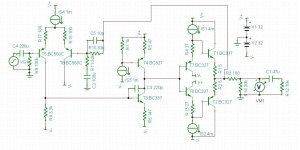
Here's the latest and last for today. I eliminated the emitter resistors in the LTP completely and adjusted R8 until 494uA was flowing through it. Since I have the constant current source set to 1mA, then the LTP should be pretty close to balanced. The bias on each base is within 1mV or so. Distortion at 1kHz, 707mVrms was 0.0054%, into a 10kohm load as shown. I'm now having trouble getting it to roll off at some MHz, since C3 and C5 don't seem to be doing it no matter what I adjust their values to. I think I adjusted R6 as well for minimum distortion.
I experimented with the buffer on it's own and found that the constant current diodes provide a lot of reduction in distortion, so they are staying in spite of the fact that they cost 10 times the cost of a resistor.
Thanks for all the help everyone.
I experimented with the buffer on it's own and found that the constant current diodes provide a lot of reduction in distortion, so they are staying in spite of the fact that they cost 10 times the cost of a resistor.
Thanks for all the help everyone.
Attachments
Fascinating thread to join late and follow the evolution! It's also interesting to see how much we're treating Simland as reality.
Most all of the suggestions have been excellent and have helped the circuit evolve to something fairly decent. One remark a bit back that needs addressing: when the overall loop is closed, you should expect the distortions measured within the loop with your (presumably high-Z) simulation voltmeter to be highish, given all the nonlinearities that global feedback is correcting. This is a good sign, not a sucky one.
Another remark that passed unnoticed (or I missed it): the noise at the input should be dominated by the source impedance, given a sufficiently large coupling cap, unless this source Z is very high (and it's probably not). Making the input resistor smaller will reduce gain by loading the source component, and the net result will be poorer. Resistor thermal noise is not some voltage source that imposes its level across anything to which it's connected --- the voltage noise generator is in series with the resistor. It is true that when the coupling cap Z gets large at low frequencies you will start to see more base current noise effects, but this should properly be mostly infrasonic.
So noting that, although you are (I hope) planning on a.c. coupling at the output to your sub amp as well as retaining the input coupling cap to your source, if low d.c. offset is desired the practice is to have the d.c. resistance seen at each base of the LTP the same. Since on the right you have 33k, best practice (absent other considerations) would be to make the input termination resistor the same value.
This is slightly academic, since the signal from the LTP is taken from just the one collector, it's already going to be difficult to provoke a balance and a low d.c. offset voltage, probably the original designer's motivation for adding the potentiometer in the emitters --- although he has cap coupling in and out, and with the low gain at d.c. ought not to have required such "balancing".
Seeing a circuit like this makes one want to explore repurposing the parts budget for higher performance, but I wouldn't encourage going too far with that until you've gotten round to actually building something.
What a great learning experience! Coming from a background of tubes I trust you're nonetheless aware of the unforgiving nature of sand-state. Component failures are very easy to induce with a slip of a probe, and you don't have the warning of even much of a spark most of the time, let alone noticing the plates of tubes glowing cherry-red
Brad
Thank you very much Brad! I will study your comments tomorrow when I have time to digest them.
Your VAS current souce is not set up correctly - Godfrey pointed you in the right direction. As it stands now, your VAS is not current source loaded. At this stage, its better to just replace T4 with a current source and re-run your sims.
Same story for the VAS emitter resistor - its too high and you are likely losing a lot of loop gain as a result.
Keep going. With this topoloigy you can get a lot better than the 50ppm you are seeing now.
Same story for the VAS emitter resistor - its too high and you are likely losing a lot of loop gain as a result.
Keep going. With this topoloigy you can get a lot better than the 50ppm you are seeing now.
Be careful with that. In the simulator, you're using perfect constant current sources. In the real world, "constant current diodes" are anything but perfect. The current can vary quite a bit with voltage, in a nonlinear way, so they may actually add distortion.I experimented with the buffer on it's own and found that the constant current diodes provide a lot of reduction in distortion, so they are staying in spite of the fact that they cost 10 times the cost of a resistor.
Disclaimer: I've never actually used them, just looked at a random datasheet yesterday to see if they're any good. Seems some are much better (or worse) than others.
but bear in mind that this is already excellent performance compared to most commercial gear.Keep going. With this topoloigy you can get a lot better than the 50ppm you are seeing now.
- Status
- This old topic is closed. If you want to reopen this topic, contact a moderator using the "Report Post" button.
- Home
- Source & Line
- Analog Line Level
- discrete op amp