Speaking of Mr. Groner... Click
A lot of constant current sources in that schematic!
Where in this circuit could I put some constant current diodes? I was thinking of replacing R4 and/or R3, as well as Q3 (replace R10 with a wire) or R9 with them. I'd delete the voltage divider if I replaced Q3 since it wouldn't be needed.
Well, I'm certain I can replace R4 (the tail resistor) with a CCD, but I just don't know the value yet. I guess I have to build it and measure the voltage drop across the resistor to figure out the proper current.
I was thinking of just replacing R7, of the biasing voltage divider, with another CCD. Here I've figured out that they intended a 1mA current flow through the divider, so I'd use a 1mA CCD.
Can someone help me with a question about this circuit? I was wondering if I would be disturbing the biasing of Q1 if I changed R1 and/or R2. As I understand it, this is a self biased arrangement, with current flowing out of the base of the PNP Q1 through R2 and then R1 to ground. In the schematic I got, R2 = 1K and R1 = 100K ohms. It seems to me that the high R1 value would add a lot of noise so I'd like to lower it.
You mean the circuit in post #1
Remember that R1 pretty much defines input impedance. Noise is the least of worries with this circuit. Also R1+R2 should equal R6 to keep bias currents the same in each transistor. It's hardly a low offset design though.
These simple circuits can work OK but if you are running it all at different voltages etc then you have to be prepared to experiment. It's an ideal circuit to learn on but you need a scope and generator to see the effect of component changes.
You mean the circuit in post #1
Remember that R1 pretty much defines input impedance. Noise is the least of worries with this circuit. Also R1+R2 should equal R6 to keep bias currents the same in each transistor. It's hardly a low offset design though.
These simple circuits can work OK but if you are running it all at different voltages etc then you have to be prepared to experiment. It's an ideal circuit to learn on but you need a scope and generator to see the effect of component changes.
Thanks! much appreciated. I figured out that the voltage divider R7 (910) and R8 (62k) draw 1mA, so I can replace R7 with a 1mA constant current diode to improve PSRR. I plan on replacing the 82K tail resistor R4 with another CCD but I don't know which value yet. R14 is 1k and R3 is 22k. Even if Q1 didn't exist, I think the current would be about 0.6mA.
What would be some of your major worries with this circuit?
Last edited:
What would be some of your major worries with this circuit?
That it won't work as well as you hope...
What do you want it to do ?
1. What supply voltage are you going to use ?
2. What gain do you really want ? A buffer is just "times 1" A circuit like this running with 100% feedback might not be happy.
3. What typical load do you want it to drive and to what levels ? For example do you want it to be able to drive 600 ohms at say 8 volts RMS or would around 2 or 3 volts RMS into 10K be enough.
They are all important basic questions.
OK, thanks. I appreciate your correspondence. For me, it's more of "what can I do with this circuit?". "How can I make it better?" (lower distortion, lower noise, etc.)
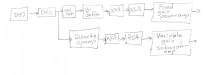
I realized, for example, that I can use this 4:1 step down transformer I have on hand with this circuit to drive an output. So, I'd want some gain to compensate for the loss in the step down transformer. As it stands now, the gain is 8, so after the transformer, the gain is 2. This is a high impedance transformer so that's good for this circuit. Anyway, it's an idea I'm kicking around. The subwoofer plate amp I have has a feature where it turns on when there's a signal present. The problem with it is that it's not that sensitive, so maybe I thought I should kick this subwoofer output up a bit to make sure it starts up. I've sat there listening to a song and the subwoofer plate amp finally decided to turn on... sigh.
I think I want to get some kind of Spice simulator, learn how to use it, and put this circuit in it.
What I have in mind is a combination DAC and preamplifier for my tiny home theater system. After listening to my Crown amps, the Musical Fidelity X-A1 that I was going to use for this system sounds like mush to me. I'd like to replace the MF amp with something that has more punch. I need to sell the MF amp.
So, this DAC preamp has two outputs, one for the subwoofer plate amp and another for the new power amps that I plan on building. The plate amp inputs are single ended and I intend that the power amps have balanced inputs. So this preamp has to drive both outputs at the same time. The input to the plate amp is 20kohms. In my small mind I figured I didn't need much to drive this plate amp, then I got scared when people on this thread warned me that this thing couldn't drive a wheel barrow down a steep hill... sigh. The output transistors are fairly hefty so I don't see a huge problem.
I'll keep the rails at +/-32V, as specified. The Borbley Shunt Regulator I ordered should work ok for that. The B1 buffer will be used between the DAC and the balanced outputs.
I want to buy a plasma TV, but since the have a lot of RFI, I need to be careful about that.
Attachments
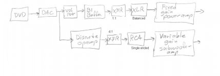
This might be easier to see.
In other words, this discrete op amp is just one part of a much bigger system.
Some of the circuits that Jensen shows for their audio output transformers shows them connected to both balanced and unbalanced jacks, but I don't know if they intend that both outputs be driven at the same time. I sent them an email with that question a while ago and they have not responded, so I don't know. It seems to me that it would be wiser to have separate driver/buffer/opamp/whatever for each output. So, that's where this whole thing got started.
Attachments
Last edited:
What's the purpose of the two transformers in that post30 diagram?
You said they were 4:1, that implies a 16:1 impedance ratio.
Are you sure what you mean when you said, they are high impedance transformers?
Sorry I wasn't more specific. Only the one for the discrete opamp output is a 4:1 type. The other, which is attached to the B1, will be a standard low impedance 1:1 output transformer. The transformers provide a host of advantages, including rfi filtering, ground isolation, and single ended to balanced conversion (for the one attached to the B1 buffer). The reflected impedance of the 4:1 transformer will be about 45kohms, so the drive transistor Q4 of the discrete opamp will have a reasonably high load. It's sort of like a single ended tube arrangement.
There is no point in using a 1:1 output transformer between an unbalanced output and an unbalanced input.
What is in the Fixed gain power amp? If it too is unbalanced input, then that's another output transformer going to waste.
Sorry if the sketch is confusing. The 1:1 transformer is connected to the single ended B1 on the input side and to a balanced XLR on the output side. The fixed gain power amp is yet to be built. I just mean it doesn't have a volume pot on it like the subwoofer plate amp does. The fixed gain amp will have a balanced input.
I ask again:
what is the purpose of the transformers?
A balanced to unbalanced input transformer inside the yet to be built power amp will perform far better than an output transformer at the Source.
Have you read any of Whitlock?
Do you really need a balanced impedance connection?
what is the purpose of the transformers?
A balanced to unbalanced input transformer inside the yet to be built power amp will perform far better than an output transformer at the Source.
Have you read any of Whitlock?
Do you really need a balanced impedance connection?
Last edited:
I ask again:
what is the purpose of the transformers?
A balanced to unbalanced input transformer inside the yet to be built power amp will perform far better than an output transformer at the Source.
Have you read any of Whitlock?
Do you really need a balanced impedance connection?
Thanks for your interest.
The 4:1 step down transformer provides a high load impedance for the wimpy discrete opamp. The 1:1 transformer obviously converts single ended to balanced. I believe I need balanced connections because of the high RFI produced by the plasma TV. Obviously the yet-to-be-built power amps will have transformer balanced inputs. Sorry I wasn't more clear.
This gets more complex by the minute.
I don't think RFI from the plasma will be an issue in practice. A bit of distance works wonders.
Driving a transformer from that opamp... that's an unknown quantity. Obviously very transformer specific, my feeling is I don't think it would be satisfactory. You need a purpose designed circuit to get the best from any transformers. Just hanging them on the output of an opamp, discrete or IC may show problems on test (overshoot, or it might provoke instability etc). You need the test gear to prove it all works OK with the very specific parts you have.
I tend to agree with Andrew on this and I think you are making it far to complex for problems that may not even exist.
This gets more complex by the minute.
I don't think RFI from the plasma will be an issue in practice. A bit of distance works wonders.
Driving a transformer from that opamp... that's an unknown quantity. Obviously very transformer specific, my feeling is I don't think it would be satisfactory. You need a purpose designed circuit to get the best from any transformers. Just hanging them on the output of an opamp, discrete or IC may show problems on test (overshoot, or it might provoke instability etc). You need the test gear to prove it all works OK with the very specific parts you have.
I tend to agree with Andrew on this and I think you are making it far to complex for problems that may not even exist.
OK, then how would you drive both a balanced and unbalanced output at the same time?
OK, then how would you drive both a balanced and unbalanced output at the same time?
I wouldn't want to use transformers tbh... but you do which is fine
") and so that is why I would want the parts in front of me to work with and develop something suitable for driving them.
and so that is why I would want the parts in front of me to work with and develop something suitable for driving them.For unbalanced to balanced and vice versa I'd probably look to an all opamp (and not discrete for this) configuration as a preferred solution. Problems such as ground loops should be able to be taken care of in the overall design and implementation of it all.
- Status
- This old topic is closed. If you want to reopen this topic, contact a moderator using the "Report Post" button.
- Home
- Source & Line
- Analog Line Level
- discrete op amp