You can add a current tap instead of resistor, so if 5mA, 480/5~=100k. Bleed resistor 100k in your sch will not drop B+ output, but it does clamp unloaded peak or floating voltage from 470V to 460V, i.e. about 10V. The other thing is that C1 can not be too large, for 5y3GT it's 22uF, but since the inrush rectifier current is limited due to the use larger input resistor R1 500 ohms, I guess that might be ok(?).
You really need to put a bleeder resistor somewhere for safety reasons.
If the software can not deal with it, at least the real world can.
On the third schematic, you have 309V on C2, and a 50mA load.
309V/100k Ohms = 3mA
Put a 100k Ohm resistor across C2. OK so the voltage will go down to maybe 308V, because the load with the 100k bleeder added is 50mA + 3mA = 53 mA.
You get the idea.
You can add a current tap instead of resistor, so if 5mA, 480/5~=100k. Bleed resistor 100k in your sch will not drop B+ output, but it does clamp unloaded peak or floating voltage from 470V to 460V, i.e. about 10V. The other thing is that C1 can not be too large, for 5y3GT it's 22uF, but since the inrush rectifier current is limited due to the use larger input resistor R1 500 ohms, I guess that might be ok(?).
Whit the regards to the inrush current, I did not get the alert from PSUD2 so it should be ok (you can try changing for test the 500 ohms to 100 ohms).
Last edited:
You really need to put a bleeder resistor somewhere for safety reasons.
If the software can not deal with it, at least the real world can.
On the third schematic, you have 309V on C2, and a 50mA load.
309V/100k Ohms = 3mA
Put a 100k Ohm resistor across C2. OK so the voltage will go down to maybe 308V, because the load with the 100k bleeder added is 50mA + 3mA = 53 mA.
You get the idea.
Then 308V will be sufficient for powering up the amp schematic? Otherwise I can decrease a little R1 (of course looking at the IFRM - 0,44mA - limit for 5y3gt) to get little extra B+ in order to achieve 310V while the bleeder resistor is in place.
Last edited:
Then 308V will be sufficient for powering up the amp schematic? Otherwise I can decrease a little R1 (of course looking at the IFRM - 0,44mA - limit for 5y3gt) to get little extra B+ in order to achieve 310V while the bleeder resistor is in place.
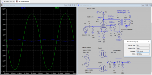
Yes, 300V is sufficient. I put it together now in LTSpice. This gives you about 5V rms over 8 ohms load or 3.1 Watts. You may need to adjust the bias by varying the value of cathode resistor of 6v6 so that it draws 50mA, depends on tube you're using. All is fine now, wish you all success and maybe send photo the progress of your amp.
Attachments
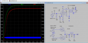
Yes, 300V is sufficient. I put it together now in LTSpice. This gives you about 5V rms over 8 ohms load or 3.1 Watts. You may need to adjust the bias by varying the value of cathode resistor of 6v6 so that it draws 50mA, depends on tube you're using. All is fine now, wish you all success and maybe send photo the progress of your amp.
Thank you so much for the clarification! How I can find the correct value of R2 (of the LTSpice model you have done)?
I will order all the components a soon as possible. Do you have also a suggestion for the layout of the chassis? (see please post*#130).
Thank you so much for the clarification! How I can find the correct value of R2 (of the LTSpice model you have done)?
I will order all the components a soon as possible. Do you have also a suggestion for the layout of the chassis? (see please post*#130).
Simply cathode voltage (also bias swing)/0.05. If bias swing determined is 12.5v, then R2=12.5/0.05=250R
The bias swing is in term decided by the gain of stage. Your screen voltage Vg2 is about 290v, the gain is somewhat higher about 22 than if Vg2 is 250v. You can reduce Vg2 to 250v by increasing screen resistor to 12k, so make it easier to refer to standard datasheet based on Vg2 of 250v . The gain would be different if you use a different OT, so the bias swing would need to be adjusted to get full output. Of course you can have slightly more bias swing for more headroom, between 12v-15v across R2 is fine
You need to consult 6v6 datasheet to determine the bias voltage using the voltage across the tube and plate current. You also need to deduce the screen current Ig2 about 3mA, so that actual Ip=50-3=47mA. If DCR of OT=200R, then 200*0.047=9.4V, and if cathode voltage (bias) is 12.5v, the Vp=300-9.4-12.5=278v.
It's easy to build as modules rather than built entire amp in one go, that you complete PSU, follow by output stage and finally front end stage and input output terminal. The components of each stage will be closed together and group together so the lead wire can be shorted, and easier to shield them.
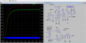
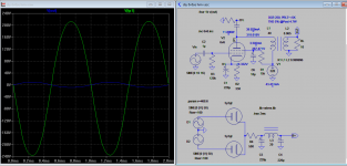
Here is another variation, the screen voltage is adjusted down to 250v and bypassed. The OT PRI Z is slightly reduced by 1K so the output is increased by about 1.5W. B+ will increase slightly by 20V and last one shown is for B+ 320V, the Pout is 5W.
Attachments
Last edited:
Seems that 6113HS James output transformer is out of stock.  can you please me provide a suitable alternative of OPT? (I have not managed to get the DCR and other information except that it is a Single Ended 3.5/5k: 0-4-8 ohm 27Hz~60KHz-2dB 60mA).
1628SEA by Hammond? http://www.hammondmfg.com/1627.htm
can you please me provide a suitable alternative of OPT? (I have not managed to get the DCR and other information except that it is a Single Ended 3.5/5k: 0-4-8 ohm 27Hz~60KHz-2dB 60mA).1628SEA by Hammond? http://www.hammondmfg.com/1627.htm
Last edited:
Seems that 6113HS James output transformer is out of stock.
1628SEA by Hammond? Hammond Mfg. - "Classic" Single Ended Tube Output Transformers - (1627 - 1642 Series)
Oh, James' is fine, still got one pair here: Match 1 pair JS-6113HS JAMES AUDIO TUBE OUTPUT TRANSFORMER EL84 6V6 275A | eBay
I heard 1628 sound rolls off at high frequent but James' does not. I don't know what DCR it has either.
Regard the layout, I like this compact design, it's really neat and nice looking to me.
Read this article to understand how to make load line simple, I hope it helps you in designing the amp if you do want to change the operating points and load.
It's been several years since I last looked at that article, but I seem to recall there were some inaccuracies in it. I recommend reading Norman Crowhurst's tutorials on this subject.Read this article to understand how to make load line simple, I hope it helps you in designing the amp if you do want to change the operating points and load.
Sent from my LG-D801 using Tapatalk
Thank you all really for the helpful support! After all this I have difficulties in finding a decent Single Ended OPT.
I managed to find another one rather than the Hammond 1628SEA.
OP5K8A 8W 5K:4-8 Ohms Single-End Output Transformer (6V6 6BQ5 6F6 7189A EL84) | eBay
Anyone have experience with this nipponic brand?
I managed to find another one rather than the Hammond 1628SEA.
OP5K8A 8W 5K:4-8 Ohms Single-End Output Transformer (6V6 6BQ5 6F6 7189A EL84) | eBay
Anyone have experience with this nipponic brand?
I think it's made in China. No experience. Here is social media video "RAPHAELITE DS6V 6V6 Vacuum Tube Integrated Amplifier Class A playing"
And Ebay list.
If you really want to buy them, probably cheaper to buy from Taobao.
And Ebay list.
If you really want to buy them, probably cheaper to buy from Taobao.
The Raphael transformer Looks nice. But the specs may be a little lacking.
Look at the UBT-2:
https://www.tubesandmore.com/sites/default/files/associated_files/p-tubt-2.pdf
UBT-2 Raphaelite
2.25 kg 1.3 kg
4800 Ohms 5000 Ohms
110 mA 80 mA
29 Henries - - -
DCR 432 Ohms (<10% of 4.8k) - - -
4, 8, 16 4, 8
Upright with end bells Potted
I have used the UBT-2 in amps. It is pretty good, even though it is not the best.
I don't know if the UBT-2 distributor sends products to Italy, but it is worth checking to see.
Tank you all, I managed to get an OPT of 12W 5k primary + 43% ultra linear 80mA 145DCR to 4, 8ohm.
I have doubt about adding a volume control. If you look at the schematic I drawn I added a 100k pot just after the RCA input. It can be good? Or is better add a volume control between the input stage and the output stage?
I have doubt about adding a volume control. If you look at the schematic I drawn I added a 100k pot just after the RCA input. It can be good? Or is better add a volume control between the input stage and the output stage?
Last edited:
The volume control belongs at the input jack, never inside a feedback loop.
Almost all tube amp designers tacitly mean to use 1/2W resistors unless specified otherwise, but you should also think about resistor voltage ratings. In this case, Rfb probably should be uprated to 1W or 2W just to insure good linearity with large signal voltages across it.
Almost all tube amp designers tacitly mean to use 1/2W resistors unless specified otherwise, but you should also think about resistor voltage ratings. In this case, Rfb probably should be uprated to 1W or 2W just to insure good linearity with large signal voltages across it.
- Status
- This old topic is closed. If you want to reopen this topic, contact a moderator using the "Report Post" button.
- Home
- Amplifiers
- Tubes / Valves
- Direct-Coupled Amplifier with Cathode Follower by R.H. Bates