They are there, often times they are just not shown in the schematic. Look at the picture of the amp in the link you posted. Notice the volume control on the front panel along with a power switch.
Yes I noticed the volume control in the pics but according to the schematic it is an addition by the maker of the amp. In any case, is the schematic attached correct? I think I should remove the two resistors of 1.5k and 270k, am I right? Sorry for the horrendous drawing

And with regard to the PSU, is it possible use the one of the Mr.Bates's amplifier (maybe adding a 1/2w resistor just before the b+ to the otp)?
Attachments
Last edited:
Tone controls are not that common. If you want one it is easy enough to find a schematic of a tone control and put it before the amplifier stages. Adding a volume control is also very easy. Some people put the volume control in an external preamplifier.
Thank you for the suggestion. Why tone controls are not that common? (i.e increasing of amount of distortions)? Secondly, I'm trying to add the volume control in the schematic to the amplifier because I'm not brave enough to start thinking about a preamplifier
better take small steps.
Last edited:
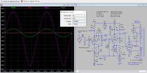
Here's what I worked up. I chose 6L6GC as output tube run as pentode since you said you wanted something approaching 10W output. This will do about 8W
Since you said you wanted good low impedance drive to the transformer primary, I figured you would want to maximize the feedback. The amount of feedback possible will depend on the current swing that the input tube is capable of. I chose a medium-size pentode for the input tube (6AU6) for the initial cut. The input tube could be made smaller to use the tubes you already have or you could purchase something in the same class as 6AU6. Of course, you could also go crazy with feedback and use an EL84, but you would probably have to add another gain stage to the amp to get better input sensitivity.
I thought it might be fun to have variable degeneration in the input stage and put a pot to do that in the cathode resistor of the input stage. If I were building this, I would like to see what effect this had in a breadboard version and would probably use fixed components in the end product.
If direct-coupling is desired, this output stage could be reconfigured like BinaryMike's design, although I don't think that direct-coupling offers any tangible benefits here and will just produce extra heat, especially if you use a 6L6GC.
Attachments
Thank you for the suggestion. Why tone controls are not that common? (i.e increasing of amount of distortions)? Secondly, I'm trying to add the volume control in the schematic to the amplifier because I'm not brave enough to start thinking about a preamplifier
I consider tone controls to be a "pre-amplifier." If you have tone controls in a power amplifier, that is just an integrated pre-amplifier and power amplifier. Semantics I guess.
Tone controls have to be outside the amplifier's feedback loop (almost always). When you draw out an amp and a set of tone controls on paper, they will actually look like separated blocks.
Having said that, I just revamped some Bogen Chb100 amps and ended up leaving the tone controls in (another RCA input bypasses them).
Having said that, I just revamped some Bogen Chb100 amps and ended up leaving the tone controls in (another RCA input bypasses them).
If direct-coupling is desired, this output stage could be reconfigured like BinaryMike's design, although I don't think that direct-coupling offers any tangible benefits here and will just produce extra heat, especially if you use a 6L6GC.
Bias stability is probably good enough with conventional cathode bias, but there is still one overwhelming advantage to direct coupling: elimination of grid blocking distortion. This is a particularly nasty artifact of transient overdrive, where the coupling cap charges to a higher voltage due to grid conduction in the power tube. Grid bias then remains elevated and shifts the power tube's operating point for a long time after the transient has passed. I personally feel that direct coupling is worth substantial extra effort, but this DIY after all, and every DIYer brings different perspective to the party.
Here's what I worked up. I chose 6L6GC as output tube run as pentode since you said you wanted something approaching 10W output. This will do about 8W
Since you said you wanted good low impedance drive to the transformer primary, I figured you would want to maximize the feedback. The amount of feedback possible will depend on the current swing that the input tube is capable of. I chose a medium-size pentode for the input tube (6AU6) for the initial cut. The input tube could be made smaller to use the tubes you already have or you could purchase something in the same class as 6AU6. Of course, you could also go crazy with feedback and use an EL84, but you would probably have to add another gain stage to the amp to get better input sensitivity.
I thought it might be fun to have variable degeneration in the input stage and put a pot to do that in the cathode resistor of the input stage. If I were building this, I would like to see what effect this had in a breadboard version and would probably use fixed components in the end product.
If direct-coupling is desired, this output stage could be reconfigured like BinaryMike's design, although I don't think that direct-coupling offers any tangible benefits here and will just produce extra heat, especially if you use a 6L6GC.
Hi there, I sim this schematic with output stage consists of both UL and Cathode feedback through speaker winding, it appears that the drive requirement is much reduced, like you said, lot of feedback to go in for low distortion 6.3W rms from 400V HT. Attached link has cathode feedback in the output. See also this thread.
Attachments
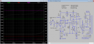
Hi there, I sim this schematic with output stage consists of both UL and Cathode feedback through speaker winding...
What does the sims have to do with SpreadSpectrum's design?Here's what I worked up. I chose 6L6GC as output tube run as pentode since you said you wanted something approaching 10W output. This will do about 8W
Since you said you wanted good low impedance drive to the transformer primary, I figured you would want to maximize the feedback. The amount of feedback possible will depend on the current swing that the input tube is capable of. I chose a medium-size pentode for the input tube (6AU6) for the initial cut. The input tube could be made smaller to use the tubes you already have or you could purchase something in the same class as 6AU6. Of course, you could also go crazy with feedback and use an EL84, but you would probably have to add another gain stage to the amp to get better input sensitivity.
I thought it might be fun to have variable degeneration in the input stage and put a pot to do that in the cathode resistor of the input stage. If I were building this, I would like to see what effect this had in a breadboard version and would probably use fixed components in the end product.
If direct-coupling is desired, this output stage could be reconfigured like BinaryMike's design, although I don't think that direct-coupling offers any tangible benefits here and will just produce extra heat, especially if you use a 6L6GC.
Thank you so much for taking the effort in design this schematic. Could you be so kind to provide a version of the schematic that use a i.e. 6sl7? How lower the output wattage will be using this type of tube? Secondly what is "variable degeneration"? Thank you again
I consider tone controls to be a "pre-amplifier." If you have tone controls in a power amplifier, that is just an integrated pre-amplifier and power amplifier. Semantics I guess.
Yes I understand that but as I said I'm looking for simplicity due to my lack of experience.
Bias stability is probably good enough with conventional cathode bias, but there is still one overwhelming advantage to direct coupling: elimination of grid blocking distortion. This is a particularly nasty artifact of transient overdrive, where the coupling cap charges to a higher voltage due to grid conduction in the power tube. Grid bias then remains elevated and shifts the power tube's operating point for a long time after the transient has passed. I personally feel that direct coupling is worth substantial extra effort, but this DIY after all, and every DIYer brings different perspective to the party.
That's true. That's an advantage if you are going to push the amp into clipping.
As far as bias stability goes, I would use an LM317 CCS as cathode resistor with a capacitor to bypass. Then bias stability is excellent.
Thank you so much for taking the effort in design this schematic. Could you be so kind to provide a version of the schematic that use a i.e. 6sl7? How lower the output wattage will be using this type of tube? Secondly what is "variable degeneration"? Thank you again
6SL7 will make a very poor input tube for this type of design. If you want to use one of the tubes you have, use the 6SJ7. This will make it impossible to use as much feedback as I had shown, so the Zout of the amplifier will be higher and damping factor will be lower as a result of using the 6SJ7. It will probably be still pretty good.
If you want to use the 6SJ7, you might as well just use BinaryMike's design. It seems pretty sound to me. It could be tweaked to use a 6L6GC as output tube or you could stick with the 6V6. I know you said you wanted something close to 10W. How would you feel with 4W or so? The 6L6GC can get you above 8W.
And to answer your other question, degeneration is what happens when you have a cathode resistor that is not bypassed. It is a type of negative feedback that raises output impedance of the stage and linearizes it.
Variable degeneration is what happens if you were to use a pot as a cathode resistor and connect the wiper to the bypass cap. You can adjust the amount of degenerative feedback.
I thought this would be a good idea since it might be possible that there could be some distortion cancellation between the output tube and the input tube at some optimal point. If I were building this amp I would breadboard the first version and play with that adjustment and see what happens.
Yes I understand that but as I said I'm looking for simplicity due to my lack of experience.
Build the amp.
It will work.
Then build another amp...
Don't worry about what these folks are throwing around, that's what they do, they're addicted DIY'ers!!
For a volume control, you can just put a potentiometer, usually an audio taper of a value ~100kohms +/- a bunch mounted in the chassis, connected to the input jack.
As in the schematic - but include a high value resistor from the grid to ground (1meg?) as a "safety", in case the pot opens and then there would be no connection
from the grid to ground, so no bias.
Tone controls go "outboard" these days, IF you choose to use any.
Many people don't since they create problems of their own, but they do adjust bass and treble, etc...
_-_-
Last edited:
But, the thing that I'm not seeing in this amp is why the 6k primary impedance on the cathode?? That ought to want to see a low Z impedance. And then where is its return to ground??
One might expect a 600ohm to VC type xfmr?
Looks like it is through R3 & R5 = 1300 ohms??
Often the means for getting driver swing for cathode follower outputs is a bootstrapped driver...
One might expect a 600ohm to VC type xfmr?
Looks like it is through R3 & R5 = 1300 ohms??
Often the means for getting driver swing for cathode follower outputs is a bootstrapped driver...
Last edited:
The tube wants to see about the same load (2-3x Rp) regardless of whether it is in the anode or cathode. Think of a 12AU7 cathode follower. We don't use a 1k resistor in the cathode; we usually use 15-20k.
Here's a good article from TubeCAD:
cathode-follower output stage part-2
Here's a good article from TubeCAD:
cathode-follower output stage part-2
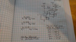
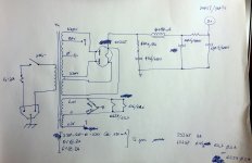
Firstly thank you all for the valuable information provided. Secondly I attach a schematic of a PSU that I had designed. Is this PSU suitable for the RH RH807 (with 6sl7 or 6sj7 and 6v6) design and for the BinaryMike's design (6sj7 and 6v6 - I'm not sure about the b+ am I right that this amp requires two 320V b+?)? Could anyone be so kind to test it on PSU (I have no clue how to use it) in order to get the value of the B+?
The power transformer is 320-50-0-320V @ 120mA - 5V*@*2A - 6.3V @ 2A.
The power transformer is 320-50-0-320V @ 120mA - 5V*@*2A - 6.3V @ 2A.
Attachments
Last edited:
Yes I understand that but as I said I'm looking for simplicity due to my lack of experience.
If you are trying to simplify things, it would be better to buy a preamp with tone controls. Building a SE amp is way easier than building a preamp. Just working the chassis for controls needed for a preamp is a lot of work. I suggest you keep the amp basic and get a preamp to handle everything else.
Last edited:
- Status
- This old topic is closed. If you want to reopen this topic, contact a moderator using the "Report Post" button.
- Home
- Amplifiers
- Tubes / Valves
- Direct-Coupled Amplifier with Cathode Follower by R.H. Bates