First thing you need to do is decide between 6V6 and 6L6. Then we can move forward from there.
It is simple enough to add a tone control, although it will be far more complicated than the power amplifier.
Edit: sorry, it looks like you have decided on 6V6. BinaryMike's design requires a little bit less B+ than an RH807, but they are pretty close to each other. You could probably follow the RH807 schematic for power supply. It has two separate filter chokes for the two channels. I don't know if I would do that, but to each his own.
Last edited:
Yes in order to not add difficulty for now better to built the amp with a 6v6. As for the tone control I was just wondering, but I'll add for sure a volume control.
I haven't found any psu schematic for RH807 in the thread of the other forum but I prefer design my own using the components that I already have rather than buy others (brand new transformer that I never used etc).
What do you think about the psu that I designed?
Today I have build it but I was not able to measure the B+. I double checked all the schematic etc.. a soon as I can I'll post a pic of the PSU.
Thanks again for the help provided!
Last edited by a moderator:
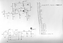
I just realized that my previous sketch is so pitiful so I just made another one with all the values of resistors and capacitor. I have built the PSU circuit on breadboard by I didn't managed to measure with a voltmeter the amount of B+.
I checked all the value before the rectifier (power transformer filaments to the rectifier etc) but when I tried to measure the B+ after the filter circuit I didn't get any value (0,56V something like that).
As soon as I can I'll upload a pic of the built PSU.
Can anyone be so kind to test the designed PSU on PSUD2 and tell me before I start get crazy in checking If it is suitable for the RH amplifier?
Attachments
Last edited:
I have slightly edited your PSU schematic position for R1 and R2 value, you should provide DCR for the choke to sim more precisely. The B+ is about 400V/305V unloaded/loaded, current drawn should be less than 50mA otherwise it just drops below 300V and exceed the current limit of the choke. You connect a 6K/20W dummy load to B+ instead of amp for testing.
Attachments
What's the purpose of R1?
To reduce the voltage for C1. This PSU has been intended to use a 6X5GT in order to obtain a higher voltage from the rectifier that can be filtered more heavily while getting approximately the same amount of B+. With a 6X5GT the voltage for C1 would be probably more than 450V.
In this case indeed R1 is not necessary.
Last edited:
I have slightly edited your PSU schematic position for R1 and R2 value, you should provide DCR for the choke to sim more precisely. The B+ is about 400V/305V unloaded/loaded, current drawn should be less than 50mA otherwise it just drops below 300V and exceed the current limit of the choke. You connect a 6K/20W dummy load to B+ instead of amp for testing.
Thank you for being so kind to test this PSU.
The DCR of the choke is 270ohm. As for the current drawn I do not know the amount precisely, this PSU should be used with the amp indicated in the schematic that I drawn. It is a modified version of a RH tube amp and considering other PSU of other different RH amps (i.e. RH 84 - Tube Audio ...... RH DESIGN) a choke of 50mA should be enough.
What you think and what you suggest?
I have slightly edited your PSU schematic position for R1 and R2 value, you should provide DCR for the choke to sim more precisely. The B+ is about 400V/305V unloaded/loaded, current drawn should be less than 50mA otherwise it just drops below 300V and exceed the current limit of the choke. You connect a 6K/20W dummy load to B+ instead of amp for testing.
Would you also be so kind to explain me the change of value for R2? Thanks.
Would you also be so kind to explain me the change of value for R2? Thanks.
R2 is decreased to maintain B+ 300V @50mA B+, or 60V drop instead of 110V drop if unchanged, about 240V B+ loaded which is not enough for the amp.
If you want to reduce the peak voltage below 450V so it does not exceed the cap rating, it's better to use breeding resistor, such as 1Meg or less to clamp the unloaded voltage down, anyway most 450v cap can take extra +10% above the rating.
Regard to RH84SE, EL84 is in pentode mode so the gain is quite high, care should be taken to keep the screen voltage stable enough so it does not motor boat or oscillate.
Last edited:
I completed two design for the amp chassis. Which one you think is more suitable? (I kept in mind some guide lines in order to minimize hum - position etc. - and to simplifying point to point wiring from different components.
Notice: all quotes are expressed in centimeters.
Notice: all quotes are expressed in centimeters.
Attachments
R2 is decreased to maintain B+ 300V @50mA B+, or 60V drop instead of 110V drop if unchanged, about 240V B+ loaded which is not enough for the amp.
If you want to reduce the peak voltage below 450V so it does not exceed the cap rating, it's better to use breeding resistor, such as 1Meg or less to clamp the unloaded voltage down, anyway most 450v cap can take extra +10% above the rating.
Regard to RH84SE, EL84 is in pentode mode so the gain is quite high, care should be taken to keep the screen voltage stable enough so it does not motor boat or oscillate.
Thank you for the clarification. So, after these modification the PSU will be ok in order to powers the schematic I drawn?
Cautions:
1. A 1 meg Ohm bleeder draws less than 1/2 mA. That is not going to keep the unloaded voltage low for a power supply that is made for a 50 mA draw.
Most indirect triodes take about 11 seconds for cathode warm up.
2. Suppose you are going to open up the preamp and probe around after power down, or solder in a new mod. It will take a very long time for B+ to discharge.
The most rapid discharge after power down, will occur when the tube cathodes are still a little bit warm.
Suppose the warm cathodes draws B+ down to 100V.
The capacitance is 47 + 220 + 220uF = 487uF
A 1 Meg Ohm bleeder resistor and 487uF has a time constant of 487 seconds.
From 100V, it is going to take 487 seconds to bleed from 100V to 63V.
If the warm tubes draw the B+ down to 50V first, then there will still be 31.5 Volts after 487 seconds.
You might use a 100k 5 watt resistor for the bleeder. The time constant is 48.7 seconds.
That is a little bit better.
3. Always check the B+ of a "powered off" amp before you go probing around.
Cautions:
1. A 1 meg Ohm bleeder draws less than 1/2 mA. That is not going to keep the unloaded voltage low for a power supply that is made for a 50 mA draw.
Most indirect triodes take about 11 seconds for cathode warm up.
2. Suppose you are going to open up the preamp and probe around after power down, or solder in a new mod. It will take a very long time for B+ to discharge.
The most rapid discharge after power down, will occur when the tube cathodes are still a little bit warm.
Suppose the warm cathodes draws B+ down to 100V.
The capacitance is 47 + 220 + 220uF = 487uF
A 1 Meg Ohm bleeder resistor and 487uF has a time constant of 487 seconds.
From 100V, it is going to take 487 seconds to bleed from 100V to 63V.
If the warm tubes draw the B+ down to 50V first, then there will still be 31.5 Volts after 487 seconds.
You might use a 100k 5 watt resistor for the bleeder. The time constant is 48.7 seconds.
That is a little bit better.
3. Always check the B+ of a "powered off" amp before you go probing around.
The PSU is intended to use a 470/5W in any case do you think it is ok or it is too much low and is better a 100k/5W as you suggested? And what do you think about the PSU? Do you agree that can be used for power up the amp circuit (Rh, 6v6, 6sl7) as stated by Known?
In any case thank you for the suggestions.
Last edited:
I am not sure which schematic you are considering, post # 123?
I did not understand why you had a resistor that was in series with the first filter capacitor.
Post # 125?
If you want less B+ Voltage:
1. Use choke input supply (50mA will require at least 7H choke, use a 10H choke).
That configuration does not have any capacitor before the choke. But you get more ripple that way, so move the cap that 'was' before the choke to 'after' the choke.
2. Use a "modified choke input" supply with a 10H choke, but with a low uF first capacitor before the choke, i.e. 1uf to about 4uf (that range may get you the B+ voltage you are trying to get to. Post #125 has about a 30uf cap there, just use a smaller uF first cap, and then move the 30uf to after the choke.
You will have to adjust the value of the first capacitor to get the desired B+ voltage (but be sure to do this with the proper load on the supply. i.e. a 300V B+ @ 50mA = a 6000 Ohm resistor. 300V * 50mA = 15W, so use at least a 25W resistor for the testing (it will get hot).
Make sure that all filter caps voltage rating can withstand the voltage of the power supply when it does not have a load. In fact, it will not have a load until the preamp tubes warm up.
A bleeder resistor is connected ACROSS the filter cap, not in series.
You need to put the bleeder so that it discharges the B+, for safety reasons.
There is no need to reinvent the wheel here. The RH Universal amp with the version 2 driver tube section with just 6l6, just 6v6, and combo 6v6/6l6 which requires a switchable power tube bias resistor. I have built all of those versions and they all turned out sounding great. The circuit that you drew is almost exactly like RH amps anyway, except for the values of your components.
I am not sure which schematic you are considering, post # 123?
I did not understand why you had a resistor that was in series with the first filter capacitor.
Post # 125?
If you want less B+ Voltage:
1. Use choke input supply (50mA will require at least 7H choke, use a 10H choke).
That configuration does not have any capacitor before the choke. But you get more ripple that way, so move the cap that 'was' before the choke to 'after' the choke.
2. Use a "modified choke input" supply with a 10H choke, but with a low uF first capacitor before the choke, i.e. 1uf to about 4uf (that range may get you the B+ voltage you are trying to get to. Post #125 has about a 30uf cap there, just use a smaller uF first cap, and then move the 30uf to after the choke.
You will have to adjust the value of the first capacitor to get the desired B+ voltage (but be sure to do this with the proper load on the supply. i.e. a 300V B+ @ 50mA = a 6000 Ohm resistor. 300V * 50mA = 15W, so use at least a 25W resistor for the testing (it will get hot).
Make sure that all filter caps voltage rating can withstand the voltage of the power supply when it does not have a load. In fact, it will not have a load until the preamp tubes warm up.
A bleeder resistor is connected ACROSS the filter cap, not in series.
You need to put the bleeder so that it discharges the B+, for safety reasons.
Exactly. There are in the same sketch the PSU schematic, the RH 6V6/6SL7/5Y3GT SE and the list of the components.
schematic.
The R1 was placed in order to keep the voltage after the rectifier lower than 450V for the C1 capacitor (470u/450V). That's because the PSU was originally intended to use a 6X5 capable of more output than a 5Y3.
From what I understand you are suggesting to remove R1 because in this case is useless (and I totally agree) and place in parallel of C1 a bleeder resistor of 100K/5W or less keeping the rest of schematic unmodified right?
Regarding the B+ I need approximately 310V B+. As soon as possible I will try to measure the amount adding a load ?/20W (what value you suggest?) resistor.
If the B+ will exceed I have to follow your point 1 or 2 right according to the solution I choose (put the C1 after the choke or change its capacitance) right?
Attachments

Last edited:
Bleeders are supposed to be used for safety (to discharge the capacitors when you turn the power off).
Bleeders are not supposed to be used for reducing the power supply voltage.
1/2 the secondary is 340Vrms = 480V peak (capacitor input supply, like you have).
Even with the tube rectifier drop (about 60V), you are not easily going to get down to 310V.
1/2 the secondary is 340Vrms = 306V average (choke input supply).
Now, for a modified choke input power supply (or call it a modified capacitor input power supply):
I think you are on 50Hz power, so that is 100Hz full wave rectified.
0.5 uF at 100 Hz is about 3200 Ohms capacitive reactance.
3200 Ohms * 0.50A = 160V peak to peak on a first cap that is 0.5uf, the middle of that is about 80V.
480V peak - 60V rectifier - 80V 1uF input cap = 340V
Now we are getting somewhere. To get to 310V, we need an additional 30V drop.
30V/0.05A = 600 Ohms. Put that in series with the 20Henry choke.
Be sure to remember to put a 100k Ohm bleeder across the first cap.
Look at the power supply schematic (it is hard for me to read the parts, i.e. R1, C1, etc., but this should describe the circuit:
5Y3 filament; 0.5uf and 100kOhm to ground; 20 Henry choke in series with 600 Ohms; Capacitor to ground; series resistor to next capacitor; capacitor to ground. Those are the nodes.
Done
Oops, that is 480V peak, -60V rectifier, -80V 0.5uF input cap = 340V
(not 1uF input cap, as I wrote above).
If you use more than 50 mA, or if you use less than 50mA, you will get something
other than 310V. Just adjust the 600 Ohm resistor accordingly (that is in series with the 20 Henry choke).
(not 1uF input cap, as I wrote above).
If you use more than 50 mA, or if you use less than 50mA, you will get something
other than 310V. Just adjust the 600 Ohm resistor accordingly (that is in series with the 20 Henry choke).
It's better also to relabel all the values on PSU schematic, using PSU2, as OP requested, and OP himself should learn to use it to help clearly see (there are lot data on PSU2) what the changes and effects which can take a long time to calculate and avoid mistakes.
My main concern is about 50mA through 2.2k is 110V drop in the B+ output, So I don't think you're going to get anywhere near 300V. So maybe the power output stage should be connected to PSU right after the choke, and connect the front-end and screen after 2.2k resistor or you decrease the value.
My main concern is about 50mA through 2.2k is 110V drop in the B+ output, So I don't think you're going to get anywhere near 300V. So maybe the power output stage should be connected to PSU right after the choke, and connect the front-end and screen after 2.2k resistor or you decrease the value.
First of all thank you for all the suggestions.
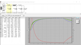
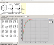
Finally I managed after some attempts to clearly understand PSUD2.
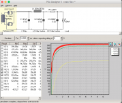
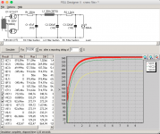
Here attached are three different PSU.
The first is the one I drawn at the beginning (with the exception of R1).
The second is the one drawn by Koonw.
Seems that both are not suitable for providing a B+ of 310V.
The third one is the one I just drawn and appears to provide a B+ of 309,24V (T1, L1 with the correct DCR).
What do you think? I think is not possible insert a bleeder resistor to C1 with PSUD2 so does it will influence the B+ amount?
Finally I managed after some attempts to clearly understand PSUD2.
Here attached are three different PSU.
The first is the one I drawn at the beginning (with the exception of R1).
The second is the one drawn by Koonw.
Seems that both are not suitable for providing a B+ of 310V.
The third one is the one I just drawn and appears to provide a B+ of 309,24V (T1, L1 with the correct DCR).
What do you think? I think is not possible insert a bleeder resistor to C1 with PSUD2 so does it will influence the B+ amount?
Attachments
Last edited:
- Status
- This old topic is closed. If you want to reopen this topic, contact a moderator using the "Report Post" button.
- Home
- Amplifiers
- Tubes / Valves
- Direct-Coupled Amplifier with Cathode Follower by R.H. Bates