Hello to everyone.
I "almost" managed to complete building the amp.
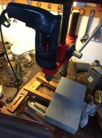
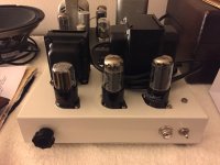
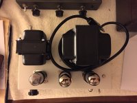
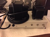
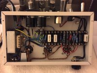
The metal work has been a pain but I ended with a good looking result as you can see from the picture.
I just finished to connect all the wires and test the amp.
The result is that the amp is completely death. No hum no noise etc. and no signals touching the input. I quickly take some measurements with the voltmeter and I noticed that at the 6V filament I have 120VAC! (hoping that I have not ruled the tubes
 ) I double checked the wires from the transformers and they seems right. There is no dispersion to ground.
Please anyone can suggest me a way to proceed in order to bring this little amp to life? As I previously said this is my second amp and the first amp completely realized and built). Tomorrow I will upload more pictures and take more measurements.
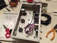
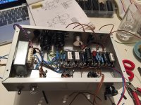
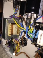
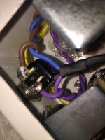
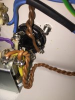
The first pictures show the cunstruction process. The latter ones show in detail the path of the 6V and 5V circuit (yellow wires to the bulb and brown wires to the filaments of the tubes for the 6V. White for the 5V).
I also measured a B+ of 340V (maybe I have to increase the R1 from the rectifier to the choke).
As regard the pure construction I added a toggle switch to select a different output impedance, a bus to collect all ground connections of the component and a star ground to collect the bus, the transformer 0 and the master earth.
I "almost" managed to complete building the amp.
The metal work has been a pain but I ended with a good looking result as you can see from the picture.
I just finished to connect all the wires and test the amp.
The result is that the amp is completely death. No hum no noise etc. and no signals touching the input. I quickly take some measurements with the voltmeter and I noticed that at the 6V filament I have 120VAC! (hoping that I have not ruled the tubes
) I double checked the wires from the transformers and they seems right. There is no dispersion to ground. Please anyone can suggest me a way to proceed in order to bring this little amp to life? As I previously said this is my second amp and the first amp completely realized and built). Tomorrow I will upload more pictures and take more measurements.
The first pictures show the cunstruction process. The latter ones show in detail the path of the 6V and 5V circuit (yellow wires to the bulb and brown wires to the filaments of the tubes for the 6V. White for the 5V).
I also measured a B+ of 340V (maybe I have to increase the R1 from the rectifier to the choke).
As regard the pure construction I added a toggle switch to select a different output impedance, a bus to collect all ground connections of the component and a star ground to collect the bus, the transformer 0 and the master earth.
Attachments
-
 IMG_1538.jpg371.6 KB · Views: 434
 -
 IMG_1542.JPG792.9 KB · Views: 424
 -
 IMG_1556.JPG857.1 KB · Views: 411
 -
 IMG_1560.JPG838.7 KB · Views: 402
 -
 IMG_1561.JPG870.2 KB · Views: 348
 -
 IMG_1562.JPG784.8 KB · Views: 107
 -
 IMG_1570.jpg388.4 KB · Views: 108
 -
 IMG_1569.JPG873.5 KB · Views: 103
 -
 IMG_1567.JPG948.1 KB · Views: 145
 -
 IMG_1564.JPG973.3 KB · Views: 132
Last edited:
I managed to resolve the problem of the heater voltage. The fault was probably of a twisted wire with a damaged insulation that touch the cathode of the 6V6. This little ****** trick costs me a NOS 6v6 and a 6sl7 GE tube. . It has been substituted and everything seems working quite well.
In any case the B+ as previously stated is 340V. Should I do something to reduce it to 310V or it is fine?
Secondly there is a sort of hum (60 cycles I suppose) that responds to the volume control. All the AC wires are tingly twisted and placed at the edges of the chassis so I don't know were is the source. I have already soldered to the components board two 100ohm 2W resistors in order to create a virtual center tap for the secondary of 6,3V but I have not connected them yet. As soon as possibile I will try this and hopefully to resolve the problem.
Moreover I used a 100k linear potentiometer as volume control. Should I use a 250k linear potentiometer in order to get a input signal of greater voltage?
. It has been substituted and everything seems working quite well.In any case the B+ as previously stated is 340V. Should I do something to reduce it to 310V or it is fine?
Secondly there is a sort of hum (60 cycles I suppose) that responds to the volume control. All the AC wires are tingly twisted and placed at the edges of the chassis so I don't know were is the source. I have already soldered to the components board two 100ohm 2W resistors in order to create a virtual center tap for the secondary of 6,3V but I have not connected them yet. As soon as possibile I will try this and hopefully to resolve the problem.
Moreover I used a 100k linear potentiometer as volume control. Should I use a 250k linear potentiometer in order to get a input signal of greater voltage?
Last edited:
I would think that putting 120vac on the heater of the tubes would fry them pretty quick. Before you powered it up with tubes did you not check that the filament supplies were all reading the correct voltages?
Stupidly not
. I'm not trying to justify myself but I'm quite new to all of this so I never imagined that I had to face a problem with the heater circuit (which I tough was the simplest thing in building the amp).340V is OK for a 6V6. I summer you measured with the amp running. Just take voltage readings around the tube and calculate the dissipation, which should not be above 14W. You may need to adjust the value of the cathode resistor to get there.In any case the B+ as previously stated is 340V. Should I do something to reduce it to 310V or it is fine?
Secondly there is a sort of hum (60 cycles I suppose) that responds to the volume control. All the AC wires are tingly twisted and placed at the edges of the chassis so I don't know were is the source. I have already soldered to the components board two 100ohm 2W resistors in order to create a virtual center tap for the secondary of 6,3V but I have not connected them yet. As soon as possibile I will try this and hopefully to resolve the problem.
Moreover I used a 100k linear potentiometer as volume control. Should I use a 250k linear potentiometer in order to get a input signal of greater voltage?
The 60Hz hum suggests you probably have a ground loop between your amp and the signal source.
You should be using log or audio pots for the volume control. If you only have linear available you can trick it, by adding a fixed resistir of the same value between the wiper and ground end of the pot.
Also keep in mind the grid reference resistor at the input is effectively in parallel with volume pot, so the equivalent value is much lower. A 250k pot with a 270k grid reference resistor, comes out roughly close to 130k.
Sent from my phone with Tapatalk. Please excuse any typpos.
Last edited:
Thank you so much for the reply. I managed to greatly reduce the 60 cycles hum by connecting the "virtual" center tap to the 6V filament circuit. Now it is almost slight.
Regarding the cathode resistors how do I perform this calculation? Indeed I noticed that the 6v6 is very hot in relation to the other tubes (especially the preamp). The value of the current resistor is about 510 ohm (it as been already increased in relation to its original specification).
Moreover, you suggest me to increase the resistance of the volume pot? I choose a linear one due to the fact that I prefer it. I find the log one of another amp of mine quite annoying because the amp is at its maximum volume without having turn a quarter of the knob.
Yes, that's very important to do. You can improve further by connecting your virtual centre-tap to the cathode of the 6V6 to help "elevate" the heaters. I also think the 6V6 screen grid probably needs more filtering. I would suggest changing the 2.2k resistor on the screen grid to two 1k resistors in series,with their junction connected to ground via a 22uF or 32uF filter cap.I managed to greatly reduce the 60 cycles hum by connecting the "virtual" center tap to the 6V filament circuit. Now it is almost slight.
Measure the voltage across the cathode resistor and use I=V/R to find the cathode current. Measure the voltage across the screen grid resistor and use the same formula to find the screen grid current. Subtract the screen current from the cathode current, to get the anode current. Multiply that current value by the voltage measured between the anode and cathode. You want a result that's close to 14W for a 6V6. Also note that it's normall for power tube's to run very hot.Regarding the cathode resistors how do I perform this calculation? Indeed I noticed that the 6v6 is very hot in relation to the other tubes (especially the preamp). The value of the current resistor is about 510 ohm (it as been already increased in relation to its original specification).
That's actually a linear pot in your other amp.I find the log one of another amp of mine quite annoying because the amp is at its maximum volume without having turn a quarter of the knob.
A logarithmic or "audio" pot will give you a natural increase as you turn it across its range. This is related to the fact that how we hear loudness of sound is actually logarithmic.Very nice, clean looking build BTW!
Last edited:
[...] Measure the voltage across the cathode resistor and use I=V/R to find the cathode current. Measure the voltage across the screen grid resistor and use the same formula to find the screen grid current. Subtract the screen current from the cathode current, to get the anode current. Multiply that current value by the voltage measured between the anode and cathode. You want a result that's close to 14W for a 6V6. Also note that it's normall for power tube's to run very hot. [...]
As soon as I can I will perform the calculation and see what I get. Thank you for the clarification.
[...] Very nice, clean looking build BTW!
Thank you! I'm happy with the final result as regard the pure appearance. What I regret is the mess with the wires and the component. This due to the fact that the chassis is small so inserting components such the choke and the big filter capacitors has been a real challenge!
Hello to everyone,
during this whole period I have extensively used this amplifier with pleasure for playing 78rpm and 45rpm record using a 50's HMV record player.
Today I tried to use an older equipment fitted with a 30's electric moving iron pickup (I had no problem playing records with it using a Crate Guitar Amplifier connected via the AUX port) but connecting it with the tube amp the latter starts producing hum and the pickup seems not to responds.
Anyone knows whats happening? The 30's electric moving iron pickup has a circa 1k resistance measured by a tester to its two wires.
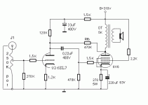
NB; attached there is the amplifier schematic.
during this whole period I have extensively used this amplifier with pleasure for playing 78rpm and 45rpm record using a 50's HMV record player.
Today I tried to use an older equipment fitted with a 30's electric moving iron pickup (I had no problem playing records with it using a Crate Guitar Amplifier connected via the AUX port) but connecting it with the tube amp the latter starts producing hum and the pickup seems not to responds.
Anyone knows whats happening? The 30's electric moving iron pickup has a circa 1k resistance measured by a tester to its two wires.
NB; attached there is the amplifier schematic.
Attachments
Last edited:
Member
Joined 2009
Paid Member
NB; attached there is the amplifier schematic.
This shematic is quite different to the amplifier named in the title of this thread, which one have you built ?
I've been interested in the Bates direct coupled cathode follower circuit originally posted by HMV130, so I just breadboarded it in stereo using 6SJ7, 7C5 (Loctal 6V6GT), and a 5Y3GT rectifier with a single rail PS. The original Bates circuit is here. My schematic is attached.
I couldn't find a 355R resistor for R5 (Bates) so I put a 350R and a 5R in series. Likewise, my OPTs (Electra-Print 5K:8R, 100mA, 15W) have a primary DCR of 163R, which is below the prescribed 250R. So I added a 75R and 12R resistor off the "ground" leg for an additional 87R (to get the needed 250R), bypassed by a 330uF electrolytic for a reasonable LF cutoff.
You will notice that some of the voltages at the same nodes vary by 10-20V between the two channels, and also that some of them are 10V or so off from Bates's schematic. It's possible that I have a bad connection somewhere, or that this is due to differences in the tubes (none of them are matched). Nonetheless, the amp is too quiet for my purposes, and I don't think finding an error would change the volume tangibly, so I won't spend time to figure it out.
Since the power output has been of interest: Playing a 1kHz test tone from my iMac, with its volume as well as the amp's volume turned all the way up, the AC voltage on the OPT's 8R secondary is 0.35V (measured by a Klein digital multimeter).
0.35 squared / 8R = .015 watt
Maybe I'm doing that incorrectly.
It sounds very nice on the 87dB test speakers on my desktop -- clean, tuneful, detailed -- but is also very quiet. Perhaps it needs more preamplification for output to speakers, even efficient ones. As-is, I would say this is a good candidate for a headphone amplifier.
Attachments
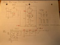
There is a couple of issues I see on your implementation. First the output tube bias is lower then the 12V target. 78V-63V=15V. That alone is not your main problem. Second the 6SJ7 at 63V is too close to the knee of the I/V curve. That could be the reason why your gain is limited. I would change, reduce R7 24K resistor and work with R5 and R2 until the output tube cathode is what it call for at 85V. Bypass R2 560R will also give you more gain also.
Note, if you get this done alright, the output would still be less than 1W with this circuit.
Note, if you get this done alright, the output would still be less than 1W with this circuit.
Thanks for the input. The grounding is done as in the original Bates schematic. Maybe people who have implemented this circuit and use it regularly, like cleantimestream, used an alternate grounding scheme?
I will poke around to see what's off, since Bates's voltages would be roughly the mean of the over- and under-voltages across the channels.
I will poke around to see what's off, since Bates's voltages would be roughly the mean of the over- and under-voltages across the channels.
jdrouin
You need to connect the bypass cap from the bottom of the output transformer primary, to ground. It needs to have enough voltage rating for the cathode voltage (DC + Signal Peak).
Otherwise, a lot of the cathode signal power is going to the 350, 5, and 1k Ohm resistors to ground. All of the cathode signal power needs to go to the output transformer primary, not to those resistors.
There may be other schematic errors, but that error is very significant . . .
. . . Low gain, low power . . . low damping factor . . .
Thanks, 6A3sUMMER. The 330uF caps are big 400V units, so I moved the negative lead directly to ground and it was noticeably louder. The voltage across the OPT secondary with a 1kHz tone and volume all the way up has gone from 0.35V to 0.75V, so slightly more than double.You need to connect the bypass cap from the bottom of the output transformer primary, to ground. It needs to have enough voltage rating for the cathode voltage (DC + Signal Peak).
This is a nice sounding circuit. As-is, it would be adequate for desktop duty, and probably quite good for headphones.
I'll see if I have resistors of values appropriate for tweaking R5-R7.
- Status
- This old topic is closed. If you want to reopen this topic, contact a moderator using the "Report Post" button.
- Home
- Amplifiers
- Tubes / Valves
- Direct-Coupled Amplifier with Cathode Follower by R.H. Bates