 Very fast!
BrianDonegan said:Thanks!
That's all Russ.
Yes, but your kitting is first class and sets the standard here on DIY audio!
It is a LOT of work, and I hope people appreciate it.. If anyone has done a GB they know what I'm talking about.
The two of you (Brian and Russ) make an excellent team. First class design and parts.
For all others, I am ONLY a HAPPY customer; I have NO affiliation with them. I only feel it is imperative to stress the quality of thier kits.
Yeah, I'm still kicking myself over the time wasted getting the right mix of components as I could only order boards from them at the time, it took quite a few upgrades before I could see what had everyone so excited. In my ignorance I did not believe components made that big a diffirence at the time.
It might even have worked out cheaper buying the whole kit (had I payed for it) , thankfully a forum memeber donated most of the components to me so I could focus upgrades on proper input caps & large tranny etc...
Also I have since built a few kit PCB's from other sources, and have never seen the quality I got from these guys.
 Thanks guys
 Banned
Joined 2002
kestrel200 said:It couldn't be so simple as just adding a jack and wiring it into the output path could it???
Thats pretty much it.
")

Headphone jacks have three tabs, one for GND, Left, and Right signal, just wire the jack to the 3 pin header either directly or via the supplied(with the kit) 3 pin connector.
I drive Senn. HD600s with my Kooka daily.
Cheers!
Russ
Banned
Joined 2002
How did you go with the build guide?
I think twistead pear audio products are so well done that the PCB is self explanatory. I checked every R and there were no mistakes (kook and My-ref).
I only have a few questions but I think I will trial-and-error (with my variac).
My boards are stuffed. I only wait for the transformers and completion of my DIY box (i have to build even my heatsinks here
 )
)If these beauties sound half as good as they look, I am lost
(my house has so many rooms lacking good stereo )
Enjoy
M
Its alive.
it works very well nice little project and great service when the PIC wasnt programmed i got a new one in the mail right away thank you..
even though i did not put the relay in yet so i have to remember to turn the powered speakers off first (event 20/20 modified amps)
the only thing is for my application it clips a bit soon. the opamp inside the PGA2311 limits the output. it is driving a +10 db line input and runs out of headroom.
It doesnt matter if the output drivers are at +- 12v since the signal is allready clipped.
i am going to do a bit of surgery and use a PGA2310 instead it should work if i just move the analog supply pins 12 and 13 to the plus and minus 12v rails instead of +- 5v? i know it has a tiny bit worse distortion figure but I can live with that
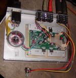
by the way you might wonder why the pot is not mounted. it is just for testing. i am going to have the pot on a remote wire in another small enclosure. by my desk. thet was the whole point of building it so i do not have audio wires running all over the place picking up noise.
it works very well nice little project
and great service when the PIC wasnt programmed i got a new one in the mail right away thank you..even though i did not put the relay in yet so i have to remember to turn the powered speakers off first (event 20/20 modified amps)
the only thing is for my application it clips a bit soon. the opamp inside the PGA2311 limits the output. it is driving a +10 db line input and runs out of headroom.
It doesnt matter if the output drivers are at +- 12v since the signal is allready clipped.
i am going to do a bit of surgery and use a PGA2310 instead it should work if i just move the analog supply pins 12 and 13 to the plus and minus 12v rails instead of +- 5v? i know it has a tiny bit worse distortion figure but I can live with that
by the way you might wonder why the pot is not mounted. it is just for testing. i am going to have the pot on a remote wire in another small enclosure. by my desk. thet was the whole point of building it so i do not have audio wires running all over the place picking up noise.
Attachments
neutron7 said:the only thing is for my application it clips a bit soon. the opamp inside the PGA2311 limits the output. it is driving a +10 db line input and runs out of headroom.
I had the same issue with my Proceed AVP driving my Alesis pwred speakers. I did sugury on the pwred speakers and changed the input gain. Now they work like a charm on "consumer" gear.
its just a bit of grounded aluminium that covers the top of the chips and signal circuit area. i dont know if it actually made any difference but it cant do any harm.
This thing is In a very electrically noisy environment with light dimmers, computers and lots of other stuff close by. so it needs all the help it can get.
it only took a couple of minutes to make. i found a tool i forgot i had
makita JS1600. lots of fun
This thing is In a very electrically noisy environment with light dimmers, computers and lots of other stuff close by. so it needs all the help it can get.
it only took a couple of minutes to make. i found a tool i forgot i had
makita JS1600. lots of fun
Hi guys,
I finally found the time to build the Kookaburra! Its sounds great!
I only have a problem with my transformer. I hooked it up for 230V and between green and brown/red there is nicely 15,8V. But there is no voltage between blue brown/red. I think there is a small cut in the wired.
Is there someone who had the same problem?
I now used an old transformer to test the kookaburra, but that one is to big to build in.
Regards Bastiaan
- Status
- This old topic is closed. If you want to reopen this topic, contact a moderator using the "Report Post" button.
- Home
- Amplifiers
- Headphone Systems
- Digitally controlled preamp/headphone amp