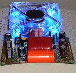
Ahahahah...Nordic is now on troubles to explain those whale capacitors
ahahahahahah!
Maybe sounded better with them Udailey...you know... unobtan....you know..ahahahahahah!
regards,
Carlos
.........................................................................................................
CRT.... La ode.... man!... i told you that?
I will start to drink tomorrow.... man!...i have written 700 milivolts from base to emitter?.... i did that?.... sure?
So.... to behave a like a drunk as i did, better to me to start to drink a lot... this way, at least, i will enjoy the beverage.... well... i am already behaving alike a drunk!...why not to relax and enjoy the VODKA with orange!
ahahahah..... 575 milivolts, from base to emitter is CELESTIAL, form heaven, just perfect, all i have dream to my amplifiers.... it is JUST PERFECT WITH 575 milivolts....forget those 700....WRONG!
regards,
Carlos
Attachments

Now talking serious... Nordic, a alot of folks in Brazil play guitar and bass
and they are asking me exactly what you have made.
Can you please give me those sketches you have made, the tube amplifier, to volume controls and all stuff drawn into a sheet of papper for me.
Also, tell me if i can publish.... will be for free to them.... for them to build, as DIY schematic.... including the HRII that is really a hell good, a hell loud and a hell enougth to guitar applications....but for bass..ehehehehe...Precision has the power!
I do play guitar (acoustic) and Harmonica at the same time and i use to dance alike western folks.... alike cowboy..ahahahah..imagine my belly where it punches down near the legs?
Harmonica and guitar are simultaneously.... to dance only few seconds..too much fat to do that for too long.
regards,
Carlos
An old friend said to me... do not discuss unobtanium
If your customer believes that blue ligth makes electron more active (pró active electrons ligth to more brigth withening results!), and if they think magnetic field will keep them together not scaping to the Universe Black holes. if they think great condensers will give them great sound...... let them be happy.... they also think their wives are beautifull and i use to say that beautifull ONLY MINE! (ahahaha.. i am biased too!)
He is rigth....ahahahahahah!... you will gonna be tired to discuss, the guy will continue to believe into those things and you may loose a friend...let it be! (Beatles music)
If you ask them if the big whale made any difference..for sure they will say yes!....of course!
Those things do not survise to blind A to B comparison testings.
I know, at least one country in Europe, were they believe that speaker sound cannot be good if speaker is over the floor, have to be over stands...metalic stands, with marble over... filled with stones, sand or whatever folks find to make them heavy and non ressonant.... go to discuss with them...a never ending subject.
regards,
Carlos
Attachments
I do also laugh when i remember those things.
Once, someone told me that his amplifier when placed into the floor sounded different compared when he installed his amplifier into a shelf... into the wall, a furniture.
He said the floor has vibrations (yes, always have some in appartments, also into houses) and this disturbs.
ahahahaha... maybe the guy is using tubes... do not know... all i know the guy is not an idiot.... maybe he knows something that i do not know.
Tubes are sensitive to vibrations..some of them are "microphonic"...you touch and you can listen the noise of your touch on the glass surface.. after your removed your finger and left a piece of skin attached to the glass because of temperature burning our fingertips.
regards,
Carlos
Hey Charly as soon as it is done and tested you are welcome to the files as always... It will probably be a one or two month project though as finances are thin after getting all my new gear...
Shame the little practice amp you get with the guitar is a joke.... sounds ok through earphones but is a joke comming through the speaker... I guess there will be a demand for valve gear until such time as transistors can clip and overdrive like valves (tubes for you americanos).
I remembered about the local tube guy last night, looking at his price list I can get away quite cheap, only the transformer is still a concern, but if I can use a 200V transformer and regulate it down to about 250VDC it should do the trick and be reasonably cheap...
I'd preffer this route to useing 3 transformers and a doubler, just because it is second hand stuff and works out cheaper. Will likely also weigh less..... noone likes hauling heavy equipment after a gig.
The reason for selecting the DX board for the outputs is that guitar speakers range from about 25 to 120W, over that gets out of my budget and would be overkill for my practice room. It is easy enough to use 2 speakers if more volume is needed.... and the front end should provide all the grunt I need even at low volume...
PS... stay out of my big components, it is only for real men....
Yep!.....big components to real man.....ahahahha....good!
I was thinking that HRII, that plays very loud, will go fine together a guitar.
I will be waiting your progress in this matter.
I can play guittar, bass and harmonica in your band... and i will be the only one able to sing in Portuguese without accent.
Will be the "king of Bossa Nova" in your place.
regards,
Carlos
Carlos or Nordic,
Will using those large transformers allow me to use smaller caps on the PSU and AMP?
My source for 4700uf caps is taking forever to even confirm if he has any and I am thinking that the 1000uf and <1000uf caps are cheap cheap cheap on ebay.
If its true, how small would you go?
Thanks
Uriah
Will using those large transformers allow me to use smaller caps on the PSU and AMP?
My source for 4700uf caps is taking forever to even confirm if he has any and I am thinking that the 1000uf and <1000uf caps are cheap cheap cheap on ebay.
If its true, how small would you go?
Thanks
Uriah
Carlos,
I saw your post about having a good size transformer and using smaller caps. You mentioned the caps on the rail could be smaller, but I dont really understand this. I dont know what the 'rail' is. When I worked at the electronics manufacturing place we would use copper bar for the poitive, negative, and ground to attach huge caps and IGBTs to. Are these what you mean when you refer to 'rail'?
So, ultimately, could you explain 'rail' and could you tell me if ALL caps that are specified to be from 470uf up to 3300uf and 10kuf could be sized down to about 1kuf or maybe even all 470uf or maybe some can be tiny and some must still be large in order to produce good bass?
Thanks again,
Uriah
Negative Udailey..... do not make economy into the condensers
after rectification, the better can be the transformer you will still have pulses.... it is a DC but alike pulses, not a nice voltage to use into amplifiers, you need condensers to fill the gaps you have, you need to release eletrons from the condenser cans when needed to produce a continuous line of voltage without fluctuations, without ripple.
How big the transformer is will not change too much this subject in my point of view, and it is a very bad idea to make economy into the condensers....you will have, as a result, a dirty low bass tone.
Man, the idea is 5000 uf to each ampere, and to each rail, and we have studied and discussed that before, in those threads about Dx amplifier... the Precision 1 thread, the Dx Amplifier thread and the group buy thread..... i would like that you use some of your time to read that stuff, as this will avoid me to repeat all the old story once again.
Also we have discussed what Doctor Self think about that subject, what Randy Slone think about that..... Nordic said what he think about that, i made my contribution too, we have discussed the condensers needed to each rail when operating into 4 ohms, also when operating into 8 ohms.... so...with a small effort you can read that stuff.
Rails....i use this word when the condensers are assembled into the audio amplifier board, to filter the positive line and the negative line.... not needed to be bigger than 470uf... also this was discussed... and deeply, and before.
Please, go back to read a little, and post your questions when the readings resulted not good for you.
regards,
Carlos
Carlos,
I am sorry to ask to many questions. I do read these posts quite a lot, but so many statements of fact end up changing as the design progresses that I dont know which statement is the final word. Honestly I do read very much on these threads and this very morning I am now reading for 3 hours and printing like mad the diagrams you made for some Brasilians that needed help on how to test the amplifier for proper voltages around C1, C2, R1, R2, R3, R4, R5, Q1, Q2, V1 AND V2.
Uriah
This is my Vanilla Uncle!
sorry uncle, in my vanilla, look's like no problem!
I was playing 1 channel fisrt (the other chanel is under construction)
Yes, this vanilla absolutely BASS Hummer. even with one channel only.
I have tested with a1837 and c4793 for driver. and no problem with that device.
about driver, it need heatsink? I had touch the driver, but this device is only go warm. no extreme heat.

Thank's Uncle!
La Ode
sorry uncle, in my vanilla, look's like no problem!
I was playing 1 channel fisrt (the other chanel is under construction)
Yes, this vanilla absolutely BASS Hummer. even with one channel only.
I have tested with a1837 and c4793 for driver. and no problem with that device.
about driver, it need heatsink? I had touch the driver, but this device is only go warm. no extreme heat.
Thank's Uncle!
La Ode
hello folks!
Udailey, please inform your supply voltage, and if you will play using 4 ohms, then i will tell you your minimum condensers to each rail and to each amplifier channel.
You may find a lot of things into the thread, as people has different needs, different voltages, different impedances.... also different cases...you are asking the "minimum capacitance"...this is different and will make the thread also bigger and bigger.
Customizing we have more data to read, but more people satisfied, and amplifiers adjusted to each different case.
Questions are good and interesting, this keep thread alive, having things to post and to discuss...but to go repeating the same stuff....heheheh..really?... not very much interesting.
Carlos
.........................................................................................................
CRT
Use heatsinks into the drivers...now warm, tomorrow more warm, and this will make it conduct more...this will make it more warm, and as a result will conduct more....and this will make it hot, and this will make it conduct more and more.... and will be more and more hot.... this will go till you will have increasings of current...and this will make it very very hot, and beeing very, very, hot it will conduct more and more and more..till you will destroy everything...put heatsinks man!...heatsinks man!
The bias stability depends that the transistors operates cold...not warm...put the heatsinks man!
You are welcome..thanks the picture and informs...but i have already told you to use heatsinks....put the damn heatsinks man!
ahahahahah...what a hell!
regards,
Carlos

Re: Power trannies
Uriah,
I have the exact transformers bought from the same ebayer. My line voltage runs around 122-125VAC, so my DC output at 41CDC under load is a bit higher than one would expect. Check your rectified DC when you have your multimeter and then deduct 3 V as per Carlos' recommendation (Thanks Carlos!)
Regards,
Francois
udailey said:
Thanks FrancoisG
I am just a baby at this DIYaudio right now so its slow going for me. I do not yet have the tools to test the output of the Transformers. They came with specs from the manufacturer. It says they should output 27.2V at 19.0A and 29.6V at No Load witha 120V input at 50Hz. So your tests suprise me. This is transformer # TI-43222C from TOROID International
Uriah
Uriah,
I have the exact transformers bought from the same ebayer. My line voltage runs around 122-125VAC, so my DC output at 41CDC under load is a bit higher than one would expect. Check your rectified DC when you have your multimeter and then deduct 3 V as per Carlos' recommendation (Thanks Carlos!)
Regards,
Francois
I have simulated using 41 volts into the output and 37 volts
to the zener diodes (22V plus 15 volts).
I have found 100 watts rms over 4 ohms, gain resistance into 560 ohms, current to each rail of 2.22A and the suggested minimum capacitance to each rail is 11.100 uF.... attention, this is for one channel only.
This is when using 4 ohms loads.... using 8 ohms loads, your power will be 65 watts rms, gonna have a reduction in sensitivity, the best resistance for gain purposes will be 500 ohms, the current to each rail will be 1.31A and the suggested minimum capacitance to
The better idea is to use around 12000uf to each rail and to each amplifier channel... so, the total capacitance for this stereo amplifier, if using a single power supply to both channels will be 24.000 uF plus 24.000 uF.... so..... HRII using 41 volts into the power supply, zeners of 22V and 15 V in series into the rail regulator will need, a total capacitance of 48000 uF, insulating voltage bigger than 45 volts DC for the stereo amplifier.
regards,
Carlos
I have simulated using 41 volts into the output and 37 volts
to the zener diodes (22V plus 15 volts).
I have found 100 watts rms over 4 ohms, gain resistance into 500 ohms, current to each rail of 2.22A and the suggested minimum capacitance to each rail is 11.100 uF.... attention, this is for one channel only.
This is when using 4 ohms loads.... using 8 ohms loads, your power will be 65 watts rms, the best resistance for gain purposes will be 560 ohms, the current to each rail will be 1.31A and the suggested minimum capacitance to
The better idea is to use around 12000uf to each rail and to each amplifier channel... so, the total capacitance for this stereo amplifier, if using a single power supply to both channels will be 24.000 uF plus 24.000 uF.... so..... HRII using 41 volts into the power supply, zeners of 22V and 15 V in series into the rail regulator will need, a total capacitance of 48.000 uF, insulating voltage bigger than 45 volts DC for the stereo amplifier.
This is the minimum suggested capacitances, to avoid "dirty" bass reproduction... bass beeing modulated by mains frequencies during strong bass tones.
regards,
Carlos
- Status
- Not open for further replies.
- Home
- Amplifiers
- Solid State
- Destroyer x Amplifier...Dx amp...my amplifier