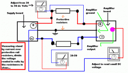
Here you will have an image showing off set measurement
And also the stand by current...the bias adjustment when the amplifier has the input shorted, no signal entering as consequence and powered.
Current will cross the protective resistances and will create a potential difference...we call that volts and it is measurable.
The DC meters will show your the voltage...divide the voltage you have readed by the protective resistance value in ohms (can be from 10 ohms till 150 ohms).... the result of your division will be the current you have...adjust your bias trimpot till you obtain a current of 40 to 50 miliamps.
Than go to the off set trimpot and adjust it to small voltage readings.
Return to the bias trimpot and check it once more...if needed, adjust it once more.
the fourth step is to check off set once more...if needed, adjust it once more too.
This is applied to every amplifier, not only DX amplifier....all decent amplifiers use to give you bias and off set adjustment trimpots.
Done it?
Now remove the protective resistances and join the wires, the resistances have separated and make an insulation to this part of the solder.... that contractive rubber insulation may be good.
Remove the short you have made in the input and them be happy playing it.
I think i have already explained that to you dear Nordic.
regards,
Carlos
Attachments
First adjustment is only a reference..for sure you will need to adjust.
Because of this adjustment need, are those trimpots beieng provide into the schematic.
Depending the transistor you will use, your supply voltage and all parts together, you may have different adjustment points related mine units.
Each one of my amplifiers had different adjustments..so... reference is only starting point of adjustment..for sure you will need to adjust.
The trimpot resistance adjustment is made before the trimpot is installed into the circuit...adjustments made with the trimpot soldered into the circuit will give you fause measurements.
regards,
Carlos
As you see...your desires are order for us
Pre programmed chips will be the future
(kidding)..for a while, stay over the posts....hehe
You have made RAJ boards...your desire will be sent to RAJ, as our board, the standard ones, already have that feature.
You see Greg!...on board biasing measuring point....the same was provided when Hugh Dean was selling Kits to be assembled...once more he have made the needed to make constructors life easier...we are learning..when he already have shown that to us.
But the idea is not to make the same as Hugh did....this idea, i think, he was one of the first to use.
He provided fuse holders soldered over the board...under the board the protective resistance was soldered...so.... measuring into the fuse holder extremes he had the bias...and then, the constructor needed only to install the fuse i place.
For sure, Hugh Dean from Aspen Amplifiers, the one produce the wonderfull Aksa amplifiers, has a brain inside the skull....his skull in not hair support only.
Also, cheap and simple amplifier cannot have bias resistances included..only to bias testing and them be bypassed to normal use...hummm, very expensive...to kits production that will be sold will be nice...but scapes from our Philosophie.
Well....Greg and Me..we are working alike mule (the hard work animal) to produce satisfaction to all folks...i hope, alike Nordic and Klaas, more people produce the amplifier.
regards,
Carlos
Attachments

All appreciated.. I'm allready well on the way with a microprosessor controler unit... first functions will just be to swich big trafos online a second or two appart. and maybe A, B, A+B outputs, later I'd like to add some monitoring and protection features here, as well as auto standby. Who knows, maybe a Little LCD for temperature display etc....
PICs are fun, I'm a little rusty but its not too hard.
BTW I think both boards have strengths and weaknesses. Just like life, we must almost always compromise....
I am getting realy exited now and doing the last touches to the amp in my head, helps ask the questions before I have enough hardware to be dangerous...
Nordic said:PICs are fun, I'm a little rusty but its not too hard.
questions before I have enough hardware to be dangerous...
Hi Nordic,
If you have some spare time, here are 3 PIC projects I'm interesting in.
1. http://sound.westhost.com/project111.htm
2. PIC controlled power board that turns outlets on in a particular order with a time delay between each, then a different turn off sequence with diferent time delays.
3. PIC based temperature and voltage monitor for recording bias settings that can be uploaded to a computer.
I think 2 and 3 would be relatively simple.
regards.
What current sockets for project 2 and how many?...? High current relays are not cheap, the 2 for my amp are about $20....
3 Will be a little harder as I don't know how to use ADC yet... have a couple of ideas though that could set 5V level triggers based on small external units like I make for model aircraft battery monitors... very small... this just needs to be connected to ports on the pic, and monitored by the programme for high status....
3 Will be a little harder as I don't know how to use ADC yet... have a couple of ideas though that could set 5V level triggers based on small external units like I make for model aircraft battery monitors... very small... this just needs to be connected to ports on the pic, and monitored by the programme for high status....
Nordic said:What current sockets for project 2 and how many?...? High current relays are not cheap, the 2 for my amp are about $20....
3 Will be a little harder as I don't know how to use ADC yet... have a couple of ideas though that could set 5V level triggers based on small external units like I make for model aircraft battery monitors... very small... this just needs to be connected to ports on the pic, and monitored by the programme for high status....
Hi Nordic,
2. The powerboard will be for my amp, preamp and squeezebox, so it is best to size the contacts for a typical DX Amp > 5 amps. I've thought of housing the PIC, relays and power outlets in the preamp.
3. I think you will find it will be very easy requiring only a couple of external components. I've seen examples in Electronics magazines. Easy to say before I actually tried it.
regards
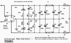
Here is the supply, this one was made for one channel.
This supply is working in my bench and it is fine.
Made for a single channel..if you want it to feed 2 channels, double the electrolitic condensers capacitance, double the bridge rectifier ampere capacity and run separated fuses to each channel.
The supply will be worst if a single one was used.
Stereo separation, audio quality and sound stage are directly connected to the use of separated supplies.
Soon this supply (tested) will be posted at Greg's Dx page.
regards,
Carlos
Attachments
Carlos - i would like to ask you to please explain a little bit better your calculations related the needed heatsink for your amplifier....
i have found the calculation earlier in this thread but it is not clear enough since you have used very rough method of calculating that do not include all the surface of the heatsink so it is a bit unclear ...
please if you have a little bit of time....thanks
i have found the calculation earlier in this thread but it is not clear enough since you have used very rough method of calculating that do not include all the surface of the heatsink so it is a bit unclear ...
please if you have a little bit of time....thanks
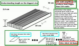
My calculations were learned during practice Sparkle, they were made to be simple,
also to be fast, not to be precise.
The main idea is to watch a heatsink you may have in your junk box and to discover how many amplifier watts can be used there...not thermal dissipation watts.....the real rms power that heatsink can hold.
It is made, dismounting the fins and calculating their area exposed to air, also calculating the base area and them comparing that area to an already known reference.
I have discovered, and was not difficult to find that a piece of aluminium, having 1 or 2 milimeters thick, having 10 centimeters side, beeing squared naturally, will have a 200 squared centimeters of area exposed to the air....and i am considering both sides to avoid confusion..
I have perceived that 200 squared centimeters of aluminium, exposed to the air, cooling by convection, were enougth to a 10 watts rms amplifier playing full undistorted power... this means that 6.24 volts of audio was beeing developed over a 4 ohms load, an undistorted audio signal..that one we use in the reality...the maximum level civilized people play..the real thing.
Having this reference i perceived that this could be very helpfull, as the electronic shops, during the sixties and seventies were unable to tell me the heatsink capacities related power it could hold....they could tell me other numbers that were not applied directly to my needs.
My need was...and still is....to discover if i can install a 100 watts amplifier in that heatsink i have found..this is the main need, the important question..other numbers did not have interest to me, as they were not enougth to fast evaluation...not enougth to direct "amplifier power" calculations.
Than, i have discover that this was linear.
1 aluminium plate, a square one, 2 milimeters thick aluminium, measuring 10 centimeters (4 inches) side, are able to hold an amplifier that was playing their 10 watts rms of music (not test signals) continuously .
Also 2 aluminium plates were tested and proved to me to be linear...as 20 watts could he hold there...if this means 27 watts of heat because amplifier efficiency.... real consumption or something alike was not my need....the real audio power..for fast evaluation were needed only.....my own need.
So, as a practical result, a simple calculation is made..... first to dismount the heatsink with your mind.... to measure and calculate the fin area, both sides if you prefer (adapted to some folks doubts)...to multiply that area by the number of fins....the last is to calculate the base are and join them together.
Lets imagine result beeig 2000 squared centimeters.... a 100 watts amplifier can be there, or 2 amplifiers of 50 watts rms..or four amplifier that can produce 25 watts rms...undistorted!...musical, not square waves full distorted power...as this do not exist in real world...this is to burn amplifiers, not to use them!....using distortion you will need, at least, 4 times more area!
You may tell that is not precise...i know that..maybe 20 percent of errors plus and minus.... the same tollerance you have in electrical circuits...and some electronic devices specified to plus and minus 20 percent.
Also you may tell that the base is covered by some fins...that the entire area is not used.... that the under of the base do not works fine for convection cooling...maybe those things are resulting in that error of precision.
I have discovered that the fins thickness do not play a good work into heatsinks..they are more for beauty and strengh than to dissipate heat...they result in delay.... the heatsink delays to be hot only...but when heated, the are exposed to air will be what command the whole thing.
This method is for normal convection position....not aplied to side heatsinks with horizontal fins...not applied to internal heatsinks that may lost 50 percent of its capacity.
I will make an sketch, as you did not shown me one, showing you how to calculate.
Strange curved heatsinks fins, those ones with different dimensions will have the need that you construct another equivalent one in your mind to calculate...and those ones depends of how experienced you are to result precise.
regards,
Carlos
Attachments
As carlos said in Engleguese More mass to surface area will only take longer to reach ambient temperature, but after that normal dissipation occurs according to actual dimensions and flowrate of coolant medium....
One way to bump the rateing of the sink up is to put it at the bottom of a taller panel, with the side causeing a chimney effect...
I will not consider fans, even if I need to mount the amp outside the house like an airconditioner...
Maybe in croatia you cook with open fire sometime... take a coffee can, remove the bottom and top and put it on your burning wood... the chimney pulls the flames through like it is a turbo unit...

Hi,
Few days ago i have cloned PSU board designed for Hi-End amplifier by Tim Giesberts (elektor 03/2005). I've just changed values of electrolytic capacitors, and did PCB my way. I hope, you will be interested.
Carlos - do you think, that this PSU is good enough for mighty Dx amp?
Few days ago i have cloned PSU board designed for Hi-End amplifier by Tim Giesberts (elektor 03/2005). I've just changed values of electrolytic capacitors, and did PCB my way. I hope, you will be interested.
Carlos - do you think, that this PSU is good enough for mighty Dx amp?
Attachments
- Status
- Not open for further replies.
- Home
- Amplifiers
- Solid State
- Destroyer x Amplifier...Dx amp...my amplifier