An European friend is starting to construct Dx amplifier to his close friends.
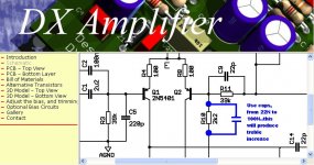
But those friends are "purists"..they do not use tone controls.... they hate those things....but...the amplifier must be adjusted to their listening room...if too much "muting" room.... absorbing high frequencies, you can compensate producing some treble boost..adjusted to your friend's taste.
Here is the idea.
Dx amplifier can be adjusted too.
regards,
Carlos
Attachments
South of our planet say hello to you.
Practice, laboratory, local Electronic Teacher.
She works near the main University here.
Image is decent...but forum is rigid about those things.... full body, decent and dressed image can be found in my mail adress..just ask.
Do you like transistors?
Mikeks is trying to track her for more than a year long...ahahahah
Her name is Leila
panzertoo@yahoo.com
regards,
Carlos
Attachments

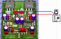
VBE multiplier board is optional and external to the main amplifier board.
There are three methods to adjust bias... some of them adjust and keep control of the bias.
The first one, the simplest one..use resistances, one fixed and another adjustable connected in series.
The second one, a little bit better, use three diodes and a small trimpot to adjustament.
The third, the most traditional one, to hard job and smaller heatsinks is the VBE multiplier.
Only the first one is supplied inside the board...there are holes to
trimpot and the resistance.
Using diodes, or VBE multiplier, you will have to travell wires, from the external board to the main board...
The diodes board and VBE multiplier board must be attached into the heatsink to receive heat.
regards,
Carlos
Attachments
Dx amplifier will be more safe using fuses.
Despite fuses can be a problem, they can help you to avoid fire if something goes short in the circuit...this is not impossible.
Fuses shows some resistance, and they use to create some sonic problems...but you can run a very thin wire from extreme to extreme, producing a guaranteed fuse of low resistance and low power in parallel with the main fuse.
Use 5 to 6 amperes fuses for the rails when working with 4 ohms....and 2.5 to 3 amperes fuses to the rails when working with 8 ohms speakers.
If your speaker has different impedance...or strange impedances, beeing very complex..prefer to use 5 to 6 amperes fuses.
The output must fuses too....as you can have big DC voltage there is something wrong happens..and this can happens in advance...while you wait the rail fuses to burn... this is a second guarantee.... alike plan B.
If you decide to use two supplies, one to each channel, use, at least, 4700uf each rail......if your supply is to be used for both channels, increase to 10000uf minimum rail capacitance.
Better to use twice of this as a guarantee that you will not have hum when some square wave continuous tone, full power, is reproduced.
2 Dx amplifiers will need less than 400 watts of power to the transformer primary circuit...so..using 120 volts, use 3.5 amps fuse...beeing 220 AC volts your mains voltage, reduce the fuse to 1.5A, or 1.75A or even 2 amperes.
regards,
Carlos
I knew the b&w's weren't the easiest loudspeakers to drive and have a fairly low efficiency, but i didn't know it was that bad.
I will try using fast fuses between ps-caps and amplifier of 5A first, and see if these will hold.
Well, lesson learned i guess
My previous experiences with the amplifier showed it was very unwilling to go into violent oscillation, even using small values for miller-cap and feedback-cap.
I have tested into heavy clipping-levels ( the sine-wave looked more like a square-wave on the scope).
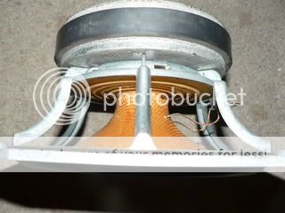
A picture of one of the woofers, 18 cm kevlar-drivers with a BIG magnet.
Also you can see some corrosion on the cast frame , they're 29 years old.
At least i've learned that the many good people in this thread will provide excellent support when needed")
Best regards,
Klaas
I will try using fast fuses between ps-caps and amplifier of 5A first, and see if these will hold.
Well, lesson learned i guess
My previous experiences with the amplifier showed it was very unwilling to go into violent oscillation, even using small values for miller-cap and feedback-cap.
I have tested into heavy clipping-levels ( the sine-wave looked more like a square-wave on the scope).
A picture of one of the woofers, 18 cm kevlar-drivers with a BIG magnet.
Also you can see some corrosion on the cast frame , they're 29 years old.
At least i've learned that the many good people in this thread will provide excellent support when needed
Best regards,
Klaas
Yes....Graham is around...and others are sniffing, ready to jump in to help us
So....no worries to make mistakes...we are protected...they will come to help us...to correct things and to adjust things.
Fuse is something that we know if they are good or bad after some burns...some accident and explosion...he is a very strange protector....he burns to tell you that you are ...... well....that is it.
You can guarantee that your fuse will behave fine related resistance it will show when new and that one appear with time.
Solder a very thing piece of wire...dismounting cables and having the thin wire that is use for shield..... sold this one into the fuse from extreme to extreme...or...sold it into the fuse socket...or...sold it between socket terminals...this will be a guarantee of low resistance...if current appear...too much current that will make the fuse blow...as it has bigger resistance than that wire, it will burn first...and that small wire...that cannot hold more than 300 miliamps will melt after the fuse...so..protection will be there..working fine...and audio will cross rails without resistances in series that may affect the power output.
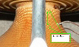
Good speaker...and opened in its back...more back pressure, and better to use inverted or omnidirectional.
Observe the part that seems to be a long neck...between the diafragm and the coil....watch if you have wavings there...if positive...use varnish to make that part more resistant.
regards,
Carlos
So....no worries to make mistakes...we are protected...they will come to help us...to correct things and to adjust things.
Fuse is something that we know if they are good or bad after some burns...some accident and explosion...he is a very strange protector....he burns to tell you that you are ...... well....that is it.
You can guarantee that your fuse will behave fine related resistance it will show when new and that one appear with time.
Solder a very thing piece of wire...dismounting cables and having the thin wire that is use for shield..... sold this one into the fuse from extreme to extreme...or...sold it into the fuse socket...or...sold it between socket terminals...this will be a guarantee of low resistance...if current appear...too much current that will make the fuse blow...as it has bigger resistance than that wire, it will burn first...and that small wire...that cannot hold more than 300 miliamps will melt after the fuse...so..protection will be there..working fine...and audio will cross rails without resistances in series that may affect the power output.
Good speaker...and opened in its back...more back pressure, and better to use inverted or omnidirectional.
Observe the part that seems to be a long neck...between the diafragm and the coil....watch if you have wavings there...if positive...use varnish to make that part more resistant.
regards,
Carlos
Attachments
Because it can be another problem...those fuses are dangerous
You discover that they are problems after they create problems to you.
They melt when transistors already have melted.... so...they protect dead transistors..maybe not to die once more..ahahahah.
In the reality they interrupt... switch off..disconect the circuit to avoid all board to melt when a short happens.
But they have resistances...measurable..when they have not those resistances when new ones..when turn old they create oxide and contact problems.
0.1 or 0.2 ohms is something you can tollerate..but sometimes resistances goes higher and this will produce reduction of voltage to the circuit...the fuse will behave alike a resistance... will reduce the voltage to the circuit..this is very common..and you can check this touching the fuse....beeing hot..means that a resistance is there.
As i told you...beeing a problem..why to multiply by two the problems..than you will have two.
Ahahaha...you are still kidding..of course you know those things.
regards,
Carlos
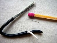
Computer microphone shielded cables have a lot of those hiper thin wires inside
Maybe you have a damaged microphone...or some computer cable that can be dismounted...a piece of audio shielded cable... a piece of good cell phone cable... a thin piece of wire that will have many "hair" inside.
Well...if you do not have..... just do not use them...but when playing your amplifier loud....and for some time (5 minutes)...put your fingers over the fuse terminals..if hot...a problem is there..if not hot...problem may come in the future....or may not.
This is a safety wire only....safety for sonics.
This one shown is not the cable of my dreams...not small enougth, but serves as an example...this one, for instances, will hold 1.5 amperes...so..if you are using 3 amperes fuse...the result may be 4.5A using this one.....not guaranteed to be this way...as normally the real fuse burns first....and them, the top limit will be 3 amps and the 1.5 will be only the second to die.
regards,
Carlos
Attachments
I hope those confused guys do not send your transformer for
Town of capes...in the place of Cape town....or number 99 in the place of 66.
ahahhahaha.
well, at least those ones are others.
Search for thinner wires...more thin than those ones shown...i hope matches size is International.....the match factory is a Swedish match company.... this one is small size, traditional, standard match size...used since 1930.
regards,
Carlos
Attachments

It is a pleasure to adjust this amplifier's off set
Setting your multi turn trimpot, or even a standard one, you will find easy to adjust to 800 microvolts reading...also you will see that your adjustment made, will be shown stable in your instrument reading screen.
"Dx amplifier, a pleasure since the beginning"
regards,
Carlos
Setting your multi turn trimpot, or even a standard one, you will find easy to adjust to 800 microvolts reading...also you will see that your adjustment made, will be shown stable in your instrument reading screen.
"Dx amplifier, a pleasure since the beginning"
regards,
Carlos
Attachments
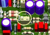
Yep, its the first time I used those trimpots, and it was realy easy to set the recommended startup resistances...
Little question, the resistors used for setting up bias in the beginning, is that between capacitor bank and amp, or between bridge rectifier and caps?
800mv useing which points to measure?
Little question, the resistors used for setting up bias in the beginning, is that between capacitor bank and amp, or between bridge rectifier and caps?
800mv useing which points to measure?
Do not worry, the amplifier is stable.
Klaas reported that had fuse burning...well...the fuse was in the wrong place (between diodes and electrolitic condenser), in the wrong time (testing) and with the wrong value (2 ampéres)
Well....Dx amplifier use much more power than those 2 amperes..the fuse burned...of course.
Normally folks..i can tell you that....99 percent of amplifiers problems are our own constructive errors.... i think i am a senior constructor and champion of errors (some of them made me learn a lot) and i ensure you that many amplifiers did not worked fine because my own constructive errors...i had some carefull not to burn their image...with one exception that was shocking to me.
As soon as Mr. Klaas fix those fuses and test it once more...the problem will finish for sure.
It is easy for us, when frustrated because our failures, to blame designers.....many times they are not guilty.
Dx amplifier is here, and to stay...posted in the best forum we have in this world...many already constructed, some of them cooking around the world, and in some years many units will be around.
Enjoy Dx now...tomorrow...or the next year...as it will be here, posted for you.
regards,
Carlos
Not a good idea to use series resistances between diodes bridge and electrolitic
condensers...we use very small inductances, and sometimes wirewound small resistances in the inductor's place...those small resistances use to be 0.1 ohms or even less (better less).
When you use wirewound resistances, you are using much more the wirewound than the resistances by itself....but of course resistance plays a part of the entire game.
I hope you have small values.....normally they are from plus to minus, from positive to ground and from negative to ground.
The rail protective resistances are the ones you will install, during your setup...externally related the amplifier, between the supply wires and and the amplifier .... the ground will travel direct to the board, but the positive and the negative wire will be cutted using a scissor...will produce two wire points, and those wire points will be soldered into the resistance extremes.
After adjustment is made..those resistances are removed and you will solder those wires, positive wire from supply to the positive wire that is going to the amplifier...also the negative wire side that comes from the supply to the negative wire that is going to the amplifier.
I will make a sketch to you dear Nordic...will be a pleasure, as others can have doubts too.
This was hardly explained many times in the forum thread, also in the home page...i am surprised that my english is too bad that doubts remains.
That 800 milivolts is just an example of a very small off set (residual voltage, dc voltage, that remains in the output line)...normally difficult to adjust in many amplifiers, some of them are not stable to measure so small voltage....you can adjust from zero (hard..very hard) to maximum of 20 milivolts...not needed to adjust to 800 milivolts or less than that, this is only an example.
This measurement is made with the voltimeter black probe point connected to the earth...the transformer's center wire and the output line, that is the place were both output emitters are connected...the input must be shorted and the bias had to be adjusted in advance.
regards,
Carlos
- Status
- Not open for further replies.
- Home
- Amplifiers
- Solid State
- Destroyer x Amplifier...Dx amp...my amplifier