Humille, troesma, humille!
Hurray, teacher!
Hi Osvaldo, nice to see you around here !
Thanks for encouraging me to continue.
")
Let's clear the grandstand that these compliments are common here, and we call any by "teacher" or "master"
Last edited:
Energy, not charge = cv^2.
No, energy is given by
W = (1/2) C V^2
Note: I use W because E is for electric field, and U for voltage.
All of the wire I currently have is 200V rated (can't strip with soldering iron).
Here, double insulated wire is rated much more than 200V, try to find the datasheet.
I've not been able to find the breakdown voltage. I thought about sealing each layer with polystyrene "Q" dope as added breakdown protection.
Try to work dry first, everything you put on the wire will increase capacitance.
200C rated, bad morning.
OK. Expected breakdown voltage about 4 KV, so no problem.
Here in Argentina, wires are rated to use at... 12V max, ja ja ja...
That's for cheap wires that you buy.
I use these
I.M.S.A.- Edflex
And there are better...
Are these KV ratings being mentioned actual working voltage ratings or voltages where breakdown or corona appear?
I would think the later and may not be all that applicable to a high reliability transformer.
Many dielectrics have high volts per mil capability but are measured with large planes (no field concentration, or edge effects or discontinuities) and for a short duration. Continuous high electric fields (especially ac) and aging of the material will lead to defects where an eventual breakdown will occur. Even good dielectrics are generally used with fields less than two hundred volts per mil.
Anyone ever try winding with what I think is called a universal wind (figure eight type pattern similar to thread on a spool)? Wires cross a lot but a given wire "sees" only wires within few turns of itself.
Thanks
-Antonio
It looks like even 130C Beldsol (Belden solder stripable) is rated for 2850V.
Some of the winding machines I've looked at run the wire through small radius turns in their tensioner. I suspect this might stress the insulation, and should be avoided.
Go ahead with the 200Cº wire, is a PITA to solder, but it's better.
For bifilar windings, you can use a thicker wire, because you will need less insulation.
A couple of turns of Teflon tape for plumbing between layers would be sufficient.
With the proposed winding scheme, you can make a layer, isolate, rest and continue with the next.
Unless you plan to make bigger transformers in the future, the windings can be done by hand, with only a support that turn the bobbin.
Are these KV ratings being mentioned actual working voltage ratings or voltages where breakdown or corona appear?
I would think the later and may not be all that applicable to a high reliability transformer.
Many dielectrics have high volts per mil capability but are measured with large planes (no field concentration, or edge effects or discontinuities) and for a short duration. Continuous high electric fields (especially ac) and aging of the material will lead to defects where an eventual breakdown will occur. Even good dielectrics are generally used with fields less than two hundred volts per mil.
When make interleaved windings, can appear big voltage gradients, between the extremes of the layers, in this winding scheme, the voltage between wires is more or less uniform.
Just in case, I avoided responsibilities in post # 79
I also use IMSA wire, incredibly good.
And obviously, that ~4KV rating, is Lab Test perforation test, in actual use that is quite derated by a good safety margin.
FWIW that Argentine wire is much stronger than the wire used in English made "Drake" brand transformers used by Marshall Tube amplifiers and the American wire used by Mesa Boogie , also in Tube output amplifiers, which is a much more stressing than any power transformer.
Tube output transformers "see" 1000V between ends when "clean", much more when overdriven into (uncompensated inductive) typical Guitar speakers and even more when the speaker cabinet accidentally unplugs in the middle of a solo .
Shorted Marshall transformer, later rewound by yours truly with Argentine IMSA "Class F" 180ºC wire:

Shorted Mesa Boogie Triple Rectifier (6 x 6L6 , 150W RMS, belonging to Argentine Rock band "La Renga) also rewound with IMSA wire:

The Mesa Boogie Caliber .22 shown below (belonging to the Argentine Rock band "Ratones Paranoicos") *also* was shorted and rewound with IMSA wire.

Just by way of comparison, the huge transformer on the left came from a 70's Fender Twin Reverb, and is made "the old way" (which can be easily seen) and is *not* dead, continues working like the first day.
I had to rewind it just because it was 117V primary only, and the Amp owner was tired of carrying a huge 220/110V transformer everywhere, *besides* his already very heavy Twin Reverb.
But it clearly was made when USA Industry led the World.
In the Globalization era that is impossible.
And obviously, that ~4KV rating, is Lab Test perforation test, in actual use that is quite derated by a good safety margin.
FWIW that Argentine wire is much stronger than the wire used in English made "Drake" brand transformers used by Marshall Tube amplifiers and the American wire used by Mesa Boogie , also in Tube output amplifiers, which is a much more stressing than any power transformer.
Tube output transformers "see" 1000V between ends when "clean", much more when overdriven into (uncompensated inductive) typical Guitar speakers and even more when the speaker cabinet accidentally unplugs in the middle of a solo .
Shorted Marshall transformer, later rewound by yours truly with Argentine IMSA "Class F" 180ºC wire:
Shorted Mesa Boogie Triple Rectifier (6 x 6L6 , 150W RMS, belonging to Argentine Rock band "La Renga) also rewound with IMSA wire:
The Mesa Boogie Caliber .22 shown below (belonging to the Argentine Rock band "Ratones Paranoicos") *also* was shorted and rewound with IMSA wire.
Just by way of comparison, the huge transformer on the left came from a 70's Fender Twin Reverb, and is made "the old way" (which can be easily seen) and is *not* dead, continues working like the first day.
I had to rewind it just because it was 117V primary only, and the Amp owner was tired of carrying a huge 220/110V transformer everywhere, *besides* his already very heavy Twin Reverb.
But it clearly was made when USA Industry led the World.
In the Globalization era that is impossible.
Last edited:
When make interleaved windings, can appear big voltage gradients, between the extremes of the layers, in this winding scheme, the voltage between wires is more or less uniform.
Just in case, I avoided responsibilities in post # 79
It also increases interwinding capacitance. Unfortunately, in my experience, there exists a compromise in low capacitance and high leackage inductance or viceversa. To have both low appears to be almost impossible.
I measure using a capacitive bridge, a piece of mylar of .05mm thickness and a piece of plumber teflon at 10KHz, and the results was the mylar to have not more than 10 to 15% more capacitance than teflon.
I used a setup like CAPACITANCE BRIDGE., using an audio oscillator isolated by means of a 12V/220V trafo, and for the null, an oscilloscope.
I also use IMSA wire, incredibly good.
And obviously, that ~4KV rating, is Lab Test perforation test, in actual use that is quite derated by a good safety margin.
Export Quality.
FWIW that Argentine wire is much stronger than the wire used in English made "Drake" brand transformers used by Marshall Tube amplifiers and the American wire used by Mesa Boogie , also in Tube output amplifiers, which is a much more stressing than any power transformer.
The coating, polyester imide resin, is extraordinary, I did not find any substance that can dissolve it, SY said to me that is a thermoset, has to be heated with the flame of a lighter, and clean it with steel wool (Virulana...) to solder it.
It also increases interwinding capacitance. Unfortunately, in my experience, there exists a compromise in low capacitance and high leackage inductance or viceversa. To have both low appears to be almost impossible.
Difficult but not impossible, Ld is easier to lower, whith adequate interleaving.
Capacitance can handle with a low dielectric constant insulation and adequate thickness.
With bifilar windings is almost impossible since the wires go together.
I measure using a capacitive bridge, a piece of mylar of .05mm thickness and a piece of plumber teflon at 10KHz, and the results was the mylar to have not more than 10 to 15% more capacitance than teflon.
I used a setup like CAPACITANCE BRIDGE., using an audio oscillator isolated by means of a 12V/220V trafo, and for the null, an oscilloscope.
Mylar ε = 3.25
Teflon ε = 2.1
Since I live almost in the country, and around my house can buy Du Pont Teflon, I think an experimental error, it is extremely difficult to maintain homogeneous teflon thickness in some areas was compressed probably, from there your results.
Maybe you should think seriously about using NOMEX, killing three birds with one stone, heat, insulation and low ε.
I use mylar for transformer insulation, but buy Nomex for my speaker voice coils.
Same stuff as used in 70's Celestion speakers ... and by Argentine LEEA speakers
I use Mylar for PTs, NOMEX for OPTs.
Do not talk about LEEA, I drop a tear...

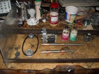
I've started collecting material to build a coil winder.
The frame will be made from old bed rails.
The motor mount on the left on a section of aluminum plate.
Bronze bushings and water harden drill rod for shafts.
I found my polystyrene Q dope and thinner, but the thinner evaporated. The bottles are probably 30 years old.
The frame will be made from old bed rails.
The motor mount on the left on a section of aluminum plate.
Bronze bushings and water harden drill rod for shafts.
I found my polystyrene Q dope and thinner, but the thinner evaporated. The bottles are probably 30 years old.
Attachments


Export Quality.
The coating, polyester imide resin, is extraordinary, I did not find any substance that can dissolve it, SY said to me that is a thermoset, has to be heated with the flame of a lighter, and clean it with steel wool (Virulana...) to solder it.
Difficult but not impossible, Ld is easier to lower, whith adequate interleaving.
Capacitance can handle with a low dielectric constant insulation and adequate thickness.
With bifilar windings is almost impossible since the wires go together.
Mylar ε = 3.25
Teflon ε = 2.1
Since I live almost in the country, and around my house can buy Du Pont Teflon, I think an experimental error, it is extremely difficult to maintain homogeneous teflon thickness in some areas was compressed probably, from there your results.
Maybe you should think seriously about using NOMEX, killing three birds with one stone, heat, insulation and low ε.
Normal commercial available nomex has not a very low dielectical constance as far a a know. Mostly it's between 3.5 and 4.5. Nomex is available in many different qualities and the harder its pressed the higher the ε is. It can be up till 8! There is a quality unpressed nomex with a ε=1.3 however this is not standard available. If anybody knows a suplier please send me a pm.
- Status
- This old topic is closed. If you want to reopen this topic, contact a moderator using the "Report Post" button.
- Home
- Amplifiers
- Tubes / Valves
- Designing an Interstage Transformer