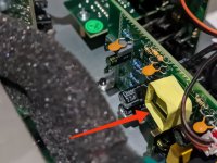
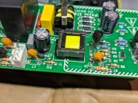
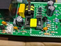
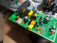
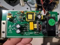
As discussed previously with EVMan, here are some pictures of the problematic "whining" mini transformer, in case anyone experiences it in the future (this is part of the STANDBY board section).
As mentioned by others here, yes I do not recommend that you tinker with the inside circuitry of the subwoofer plate amp, unless you know what you are doing (dangerous electrical components inside, as well as voided warranty if still within warranty-period).
I did it since 1.) The item already doesn't have any warranty and can't be returned anymore, and 2.) Even if it was working, the "whining" sound really makes the "working condition" unit unbearable to use (and possibly fail in the future, if there are other components actually causing the whine as mentioned by others in this thread)
My hunch is that the dark gray mini ferrite cores that are attached (loosely) to the mini transformer are the ones vibrating and causing the high pitched whine (pictures show the yellow insulating tape removed). I doot n know if they could be damped in some way or not. Experts can chime in on their opinions.
I did not bother to try and strip down the center windings anymore, as it was too cramped and it was of no use to me anymore.
Attachments
RKV- thank you for sharing. I traced out the STANDBY circuit card before sending my spare to you. I could not find good data on U5 or Q1. Because of this lack of information, the schematic is not published. However, the circuit can be broken down into three sections:
1) Input EMI filter-rectifier-filter
2) PWM circuit with flyback transformer primary
3) Output circuit with secondary, rectifier, filter with relay and driver.
Proper operation can be checked by measuring Line Voltage across P1 and P2. When Switched to AUTO (With music playing) or ON, the relay should actuate and the line voltage is present at P2 and P3. The line voltage is then applied to the main transformer. Use caution as lethal voltages are present. Troubleshooting this little power supply is made difficult by the lack of info. Although the pin out is different, the SG6848 PWM IC has very similar functionality. Q1 is probably a 600V MOSFET, but again, no data. C8 is the main output filter capacitor, It is subjected to high frequency ripple and currents.
Parts Express does not stock any spare parts nor will they reveal the manufacturer. This little SMPS presents a challenge to troubleshoot safely. My recommendation is to use "No power Applied" continuity checks after looking for buckled caps and/or burn marks. Good luck to all. EVMan
From RXV:
Hi, How are you? My brother-in-law finally arrived yesterday night, and I was able to get the standby board from him!
I will try to connect it probably within the day or tomorrow once I get to have free time to do so (so excited and a little bit scared at the same time hehehe).
For now I compared your standby board with the original board that came with my unit. Yours is version 1.1, and mine is version 1.2. Upon careful inspection, I don't see any parts that differ, only the lay-out of some components (but still same values), so it is relatively the same. C3 and C9 had different components (brand) used, but the values are the same (154J100).
I'll report back to you what I have found (and hopefully working!!!)
Thanks again!
Good morning RXV. Glad to hear that you finally got the STANDBY board. As I noted previously, this amplifier has been through several revisions. The STANDBY board is no different; parts and suppliers change all the time. In this case, the functionality remains the same. The switching power supply generates “Always on” +12 Volts. This voltage gets routed off the board to the OFF-AUTO-ON circuitry on another board via the 3-Pin connector. The OFF position maintains an open circuit while AUTO-ON will provide +12V back to Q2. If this voltage is present Q2 will conduct and energize the relay. The energized relay applies the mains voltage to the big transformer on the heatsink.
Take your time and swap one connection at a time. Mount the board with the original screws and you are ready to try it out. A couple of options here: 1. You can connect a cheap speaker or dummy load (even a light bulb can work) and 2. You can apply power all at once or use a Variac or place a light bulb in the primary circuit. The STANDBY Board has a 1 Amp fuse installed next to the black relay.
Hopefully, everything works and you spend the rest of the day listening to music. However, . . . If the new board’s transformer still whines, there is (was) a problem in the OFF-AUTO-ON circuitry (on the other board), probably a dead short. The other possibility is that a new problem happened when you powered up without the ferrite installed. It might be possible overcome either of these problems by using a jumper instead of the 3-Pin connector. Good luck- EVMan
EVMan was very kind enough to send me his spare SPA250 standby board. You're the man, EVMan! Hehehe
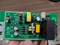
His board is version 1.1 (2012.1.13), while my original one was version 1.2 (2012.03.15). Please note that my SPA250 plate amp was just purchased in 2022, so they probably hadn't revised the standby board ever since.
Version 1.1 is almost the same as Version 1.2, except for some minor relocation of components, as well as some components have different "brands" used (but same ratings). See actual pictures below.
Inserting (and using) the Version 1.1 standby board onto my SPA250 (which originally uses version 1.2) works fine without any issues at all.
So if ever one of you guys, for some reason, have a bad/busted SPA250 standby board, you could probably look for parts-out SPA250 parts in the marketplace and replace your old one with the working one. Plug-n-play (just 2 screws + 4 connectors for the standby board). Easy-peasy.
One thing to note, EVMan's standby board's mini transformer still emits some high pitched whining sound, but it is very very negligible (around just 1/10 of mine before), and it is inaudible once you close the rear plastic cover shut, so I may assume that all SPA250 boards have this "shortcoming" or semi-flaw with regards to the mini transformer (since they didn't apply any dampening or varnish to the specific component, probably a sign of using cheap parts). It's just a matter of if you are annoyed by it or not (and can hear it).
Attachments
RKV- Thank you for the kind words. Hopefully, your SPA250 works fine and lasts a long time. The old, bad amp still has some salvageable parts, e.g. IC's, transistors, pots, etc. If anyone needs parts for a broken SPA250 plate amp, please post here or send a PM. Good luck and good listening. EVMan
And then . . . depression set in. My SPA250 failed with a bad cap- the same cap mentioned by WacGen in a previous post. That was three months ago. This morning I was out in the garage enjoying a smokey treat, when a squadron of helicopters came overhead. Only it wasn't helicopters. The sound was my subwoofer putting out enough low frequency energy to rattle the house. The unit has not been pulled yet. Two failures in three months is not desirable. Need to make choice between repairing or replacing with a mono-block type power amp.
My guess is another bad cap- The SPA250 uses ChengX capacitors and they are not reliable. If I pull the plate amp, all of the caps are getting replaced. More as the situation develops.
Best- EVMan
My guess is another bad cap- The SPA250 uses ChengX capacitors and they are not reliable. If I pull the plate amp, all of the caps are getting replaced. More as the situation develops.
Best- EVMan
These amps come in many different revisions, so your mileage may vary. My current SPA250 is circa 2016. There have been enough thermal cycles on it that the rear cover came off easily with a 1" chisel used to loosen the perimeter. There was some type of mild bonding to the rubber gasket, but no captivating hardware. Mine came off quite easily. If you move slowly, it should come off but try not to tear the gasket. The main amp and speaker leads are under the cover. A ferrite choke and two Fast-On connections are buried in a protective foam shroud. Cut the cable ties and unfurl the foam. Disconnect the Fast-On connections and the cover will separate completely from the main amp. This allows for easier troubleshooting and repair. Expect to see some bulging capacitors. Good luck- EVMan
It was 106 degrees today, so my motivation is lacking as well. I decided to pull the unit tomorrow morning while it is relatively cool and work on it inside. Just finished reviewing the schematics and photographs that were posted in this thread and all the bad memories came flooding back. Parts Express is back ordered on SPA250 Amps with expected delivery in July. My installation mandated the use of a plate amp- there is no room for a stand alone amp, not even a 1U unit. I am going to try and fix this thing. Those ChengX capacitors are pretty heinous. My 1st act will be to generate a parts list in Excel and then recap the entire unit. The main board is a bear to work on. If you do try and work on the main board, take lots of pictures and try to work over a rimmed serving tray so the small parts are contained instead of rolling around the floor. I understand your reticence to tackle this project- it ain't any fun. If you decide to continue, you can always post here or PM me directly. Best of luck- EVMan
Hi EVMan, recapping is a good idea after you ruled out other possible root cause. Otherwise, you may still end up with a bad amp with nice caps. Check all the voltage rails with a multimeter and see if they agree with the figures on the schematics (+18V, -18V, +Vcc, -Vcc). The schematics did not list a Vcc figure, but it could be anyway from 20V to 50V - the important thing is the positive and negative rails are similar magnitude.
FYI, an option I will likely do when/if my SPA250 die is to retrofit the amplifier board with a 500W Class D digital power amp: https://a.co/d/68ZvuHd. The SPA250 transformer and power supply should be able to feed this digital map module. I have heard of others on the internet doing the same when they cannot find a suitable plate map replacement.
Good luck!
@EVMan
I'm so sorry to hear this. That's also one reason why I'm hesitant in maximizing the gain/load on the plate amp, as not to over-exert it's "limits".
Yeah, this product ain't the most durable in terms of design/parts used, so all owners of this particular model might be interested in repair/replacement alternatives once their plate amp breaks (now it is a matter of WHEN )
)
@WacGen
That may be a good idea. In case a broken SPA250 is too much too repair or diagnose (or too many parts to replace), it might just be a better idea to just simply replace the necessary board(s) with a better one (assuming that you are correct with the stock power supply still being capable for re-use)
If ever you get to do it, post it here so that others might benefit for the "repair upgrade"
I'm so sorry to hear this. That's also one reason why I'm hesitant in maximizing the gain/load on the plate amp, as not to over-exert it's "limits".
Yeah, this product ain't the most durable in terms of design/parts used, so all owners of this particular model might be interested in repair/replacement alternatives once their plate amp breaks (now it is a matter of WHEN
)@WacGen
That may be a good idea. In case a broken SPA250 is too much too repair or diagnose (or too many parts to replace), it might just be a better idea to just simply replace the necessary board(s) with a better one (assuming that you are correct with the stock power supply still being capable for re-use)
If ever you get to do it, post it here so that others might benefit for the "repair upgrade"
@WacGan. Thanks for your reply. I have 45 years of electronics experience and will conduct due diligence before making any type of decision between repair, replace or modify. I still haven’t pulled the unit, but when I plugged it in this morning it played fine x 2 hours. I doubt it is a semiconductor or resistor, but anything is possible including solder joints. Capacitors are notorious for going “wonky” and doing evil things, especially as they heat up and age.
The DC rail voltage will depend on the AC mains since the power supply is unregulated. At no load, mine measured ± 65Vdc at a line voltage of 118 Vac. Loaded at 4 Ω at full power they drop to 54 Volts. The +18 Vdc is developed through a series regulator transistor/Zener combination. +9 Vdc is available through a resistive voltage divider. There is no -18 Vdc. However, the soft limiter circuit does generate ± 15 Vdc. The STANDBY Board generates +12Vdc with a small SMPS. This voltage gets routed off board to the OFF-STBY-ON circuit. If music is playing in STBY or the switch is ON, 12 Vdc is routed back to the relay to close the contacts. If there was a need, the amp could be run on my Variac to simulate high and low line conditions, but I don’t see the need. Yet.
I looked at several Class ‘D’ modules. These are hard to evaluate without good documentation and/or certified test results. A case in point- the only user comment said the amp came without any documentation at all. I can tell just by looking at the back of the circuit card what the pinout should be, but do I really want to trust an undocumented $18.95 Chinese Amplifier to drive my $400 woofer? My gut tells me no. However, if you are interested in taking that route, I would be interested in helping out or at least hearing of your experience(s). Maybe it’s time to start looking at some Class ‘D” threads on the forum . . . Cheers- EVMan
Hi WacGen. Thanks again for your reply. I bought a shelled SPA250 for parts, especially since RXV needed a STANDBY board. So hold the phone. I still have the preamp, transformer, bridge, caps, heatsink, etc. This might make a good test bed for trying some Class D Amplifier modules. This needs a ton more research and is lower priority than fixing my current problem child. It is interesting approach, no doubt about it. Best- EVMan
Hi WacGen and RXV. I looked at your linked 500W amp module and did a little research. Two threads on the forum seemed germane:
Home > Amplifiers > Class D
Post #1 Ebay amp - is 500W believable?
R13 from 100Ω to 3.01K Ω for lower gain
R11 to 8.2K Ω for symmetrical current limiting
Adjust clock frequency to 400 kHz
Post #2 Fixing [and preventing] a fried Zobel network
R36 is 10 Ω low power, swap in higher power unit
Protection- some people added fuse/relay protection for DC and speaker
My take away is these modules ship with the wrong gain setting and current limiting resistors. After modification they seem to work satisfactorily but not at 500W RMS. Still, plenty of power for a subwoofer. But that brings up a number of questions as a replacement for use in the SPA250.
This 2902 based module is a standalone power amplifier. It lacks much of the circuitry found in the SPA250 preamp (please refer to the attached block diagram):
Auto sense turn-on
Input buffering
Dual input summation
Hp Filter to eliminate infrasonic frequencies
Voltage gain block
Variable low pass filter
Volume control
0° / 180° Phase switching
Optional (switched) 6 dB Bass Boost
It really depends on what you want to achieve and what other resources that you have available. For example, if an LFE output is used, the LPF Function is built in. If you have a Mini-DSP, you can sum sources, add boost, set filter slopes and cut frequencies, and possibly add some gain if needed. Of course, this can also be done with a handful of op amps and discrete components on a custom board. Op amps usually require ± Vdc. This points to an additional power supply. All of these extras cost time and money. However, there is another viable option . . .
The SPA250 has a preamp glued to the rear panel via the RCA jacks. If the preamp is working, then it would be a fairly simple task to generate +18Vdc for power. The OFF-AUTO-ON circuit would not work, but the above functions would be enabled. Working condition is a big if. The implementation really depends on the individual user and what the end game is within the typical SWPC framework. Just food for thought. Best Regards- EVMan
Attachments
These Class D modules are all based on the iraudamp irs2092 standard application for the driver chip. If you look for the ones you find from "LJM" design, they work just like the ones with the small fan you showed.
So the constructions are not wrong. There probably have been sold x10.000 or even more.
Sound quality from the iraudamp is very good, for a sub, excelent, even as I did not use the specific module with the fan by my self. The 18$ module may be perfectly fine with your power supply. Look on what iraudamp type the cirquit is based on, check the data and you should be fine. Do not get fooled by the price, this is enough money for a Chinese industry mass product. You in the US can't even do a PCB for that money, I know .
Extracting the power amp and joining the preamp and and a D-module is a nice way of repairing an amp. Be sure to cool the heat producing semi conductors, the regulator for the IC is critical. To avoid a third voltage, there is a regulator on the heatsink, which sometimes fails. Keep it cool, just like the inductor. Inside a closed sub a fan may be OK, usualy the over temperature protection should work if not disabeled in the design. I'm pretty sure you will modify the cooling to passive, the aluminum amp plate should be plenty.
You may reposition the fan for the coil cooling.
Any way, I do not trust the components they use, as this design is build by many sub contractors. You never know what you get, price is no indicator.
A good idea is to change the Power FET's and regulator for 100% real ones, from a reputated supplier. This may cost you 6$. As an alternative run them at full load on an resistor heating up a bucket of water until they blow (or not). Usually, if fake parts are used this test shows it after 2 minutes. The construction itself is very robust and reliable. As a perfectionist you may also change the electrolitic's. Heat inside a sub may eat them in short time.
Then, have a look at the 4 Ohm power. Not all versions are made for 4 Ohm at any voltage. So you may use the max 80V only with 65V to drive 4 ohm reliable as an example. These iraudamp irs2092 modules are very close to an AB amp in the practical use. So if you have a symetric supply, you can use them as an exchange part.
What I have not experienced, but may be a point: If you use them constantly at very high output, like with an internal boosted sub, the output coil may be on the small side. So have a look how many amps the installed part may take.
As always with Chinese parts: Good luck!
So the constructions are not wrong. There probably have been sold x10.000 or even more.
Sound quality from the iraudamp is very good, for a sub, excelent, even as I did not use the specific module with the fan by my self. The 18$ module may be perfectly fine with your power supply. Look on what iraudamp type the cirquit is based on, check the data and you should be fine. Do not get fooled by the price, this is enough money for a Chinese industry mass product. You in the US can't even do a PCB for that money, I know
.Extracting the power amp and joining the preamp and and a D-module is a nice way of repairing an amp. Be sure to cool the heat producing semi conductors, the regulator for the IC is critical. To avoid a third voltage, there is a regulator on the heatsink, which sometimes fails. Keep it cool, just like the inductor. Inside a closed sub a fan may be OK, usualy the over temperature protection should work if not disabeled in the design. I'm pretty sure you will modify the cooling to passive, the aluminum amp plate should be plenty.
You may reposition the fan for the coil cooling.
Any way, I do not trust the components they use, as this design is build by many sub contractors. You never know what you get, price is no indicator.
A good idea is to change the Power FET's and regulator for 100% real ones, from a reputated supplier. This may cost you 6$. As an alternative run them at full load on an resistor heating up a bucket of water until they blow (or not). Usually, if fake parts are used this test shows it after 2 minutes. The construction itself is very robust and reliable. As a perfectionist you may also change the electrolitic's. Heat inside a sub may eat them in short time.
Then, have a look at the 4 Ohm power. Not all versions are made for 4 Ohm at any voltage. So you may use the max 80V only with 65V to drive 4 ohm reliable as an example. These iraudamp irs2092 modules are very close to an AB amp in the practical use. So if you have a symetric supply, you can use them as an exchange part.
What I have not experienced, but may be a point: If you use them constantly at very high output, like with an internal boosted sub, the output coil may be on the small side. So have a look how many amps the installed part may take.
As always with Chinese parts: Good luck!
So I finally got some time to get back to this project and have spent the past couple days carefully testing the pinouts of everything.
But first... some pics!
I actually have TWO versions of this amp. While they both look identical from the outside, and both share virtually identical looking amp boards, pre-amps, etc... it seems at some point during the production run that the auto-off functionality was drasticaly changed.
Here is ONE version that does NOT have a relay board. Basically the on/off functionality is solid-state controlled and the transformer is ALWAYS powered on:

Here is the OTHER version which DOES have the dedicated relay board. In this setup, the relay board includes a SECOND 12-15 volt power supply that keeps the pre-amp board (with it's signal detect circuitry) powered when the main amp transformer is powered off:

Here they are side-by-side for comparison:

You will notice that the one on the right (with the relay board).. I have already stripped all the amplifier components off the board.
I am getting it ready for these guys here:

The mini heatsink/fan will be removed and replaced with a thick piece of aluminum angle that attaches the amp directly to the original heat-sink.
But first... some pics!
I actually have TWO versions of this amp. While they both look identical from the outside, and both share virtually identical looking amp boards, pre-amps, etc... it seems at some point during the production run that the auto-off functionality was drasticaly changed.
Here is ONE version that does NOT have a relay board. Basically the on/off functionality is solid-state controlled and the transformer is ALWAYS powered on:
Here is the OTHER version which DOES have the dedicated relay board. In this setup, the relay board includes a SECOND 12-15 volt power supply that keeps the pre-amp board (with it's signal detect circuitry) powered when the main amp transformer is powered off:
Here they are side-by-side for comparison:
You will notice that the one on the right (with the relay board).. I have already stripped all the amplifier components off the board.
I am getting it ready for these guys here:
The mini heatsink/fan will be removed and replaced with a thick piece of aluminum angle that attaches the amp directly to the original heat-sink.
So after 2 days of spending more time mapping these out then they are actually worth, I have what many are likely looking for: the pinout!
Bench-testing both over a 48-period timespan to ensure the on/off/auto work and that the pre-amp itself works on both:

UNDERSTANDING THE PRE-AMP PINOUT:
Imagine looking at the bottom side of the pre-amp PCB with the main 6-pin connector at the top side.
The 6 wires are as follows:
1: (Green) VCC 12-18 Volt Input (confirmed this as an acceptable range)
2: (Yellow) Audio Signal Output
3: (Orange) Ground (both power and signal)
4: (Red) Protection trigger - of no use to us anymore. Ignore / not used
5: (Brown) Temp trigger - also of no use to us. Ignore / not used
6: (Black) Standby trigger - explained below.
Regarding #6 (the black wire). Each of the 2 amps I have were different. On the amp with a relay board, this pin/connection is open when the pre-amp is in standby and shorts to ground when the pre-amp is active or on (music playing).
However - on the OTHER amp (the board without a relay board), this pin is around half a volt (.6 volts to be exact) when off/standby and goes high (to whatever #1 (VCC) is when the amp is on/playing music.
More to come shortly...
Bench-testing both over a 48-period timespan to ensure the on/off/auto work and that the pre-amp itself works on both:
UNDERSTANDING THE PRE-AMP PINOUT:
Imagine looking at the bottom side of the pre-amp PCB with the main 6-pin connector at the top side.
The 6 wires are as follows:
1: (Green) VCC 12-18 Volt Input (confirmed this as an acceptable range)
2: (Yellow) Audio Signal Output
3: (Orange) Ground (both power and signal)
4: (Red) Protection trigger - of no use to us anymore. Ignore / not used
5: (Brown) Temp trigger - also of no use to us. Ignore / not used
6: (Black) Standby trigger - explained below.
Regarding #6 (the black wire). Each of the 2 amps I have were different. On the amp with a relay board, this pin/connection is open when the pre-amp is in standby and shorts to ground when the pre-amp is active or on (music playing).
However - on the OTHER amp (the board without a relay board), this pin is around half a volt (.6 volts to be exact) when off/standby and goes high (to whatever #1 (VCC) is when the amp is on/playing music.
More to come shortly...
Basic operation of the pre-amp board:
In both cases (both amp versions), the operation is pretty simple: feed the pre-amp board 12-18 volts DC at pins 1 and 3 (1/green is +, 3/orange is ground) and any signal fed into the back of the plate (via RCA jacks, speaker posts, etc) is outputed at pin 2 (the yellow wire). Audio signal ground is the same as power ground. Could not be simpler.
Now let me outline the differences if you are trying to get fancy with things.
Regarding the solid-state controlled version (no relay board)
The VCC is always hot since the main (and only) transformer is always energized. The 18 volts is supplied by the amp driver board and fed to the pre-amp board. When the pre-amp board is "on" (auto or manually), it sends a high voltage signal (typically about 1 volt less than VCC) BACK to the amp driver board - which activates the amplifier.
By providing nothing more than 12-18 volts to the VCC and Ground, the pre-amp will "power off" after a while as normal. If you wanted to "tap into" this auto-off, you can find a creative way to have the Standby output trigger a relay. I found that it seems if you do not have at least a 10k resistor across the Standby output and ground, this version will have issues going into sleep mode (when rear switch is set to "Auto").
Regarding the version with a dedicated relay board
This version is a bit more fancy but - for the sake of interfacing aftermarket amps into the chassis - is likely going to be easier to interface.
How this version works: the pre-amp board has 2 power input sources: ONE that comes from the relay board (12-14 volts typical range). This power source keeps the "auto on sensing" ability of the pre-amp functional when the main transformer (and the normal VCC) is not engergized. When the auto-on (or manual on) powers the pre-amp up, it sends a signal back to the relay baord (pinout and explaination follows) which activates the power relay - which in turn, energizes the main transformer. The main transformer then provides the full power (12-18 volts DC) to the VCC as normal. It is important to note that: the output current available from the relay board is really not sufficient to power all the op-amps and circuitry on the pre-amp board directly. It is only meant to provide enough current to keep the auto-sensing logic alive and send signal back to the relay board to "power up". I ran tests and found that in order to relaiably pass audio through the pre-amp board, you must still provide VCC and Ground with 12-18 volts.
If you wanted to - in theory - just use the pre-amp of this version in stand-alone configuration, you can simple provide the needed 12-18 volts to Ground and VCC and you are all set. Keep in mind: doing this on this version means the pre-amp is always powered on. (it will never go into sleep mode).
Bottom line: on this version... you can leave the entire relay board and pre-amp board as-is. Just know that: once you power-up, be sure to supply a clean 12-18 volt signal back into the VCC from the main supply in order to avoid stability issues with the audio signal.
REGARDING THE RELAY BOARD
This little guy is pretty simple:
1: (Red) Ground
2: (Brown) 12-15 volts output (from relay board) to provide provisional power to pre-amp when main supply is OFF
3: (Black) Trigger ON (pre-amp board sends the 12 volts TO the relay board on this line to activate the relay, which energizes the main xformer)
Whats Next?
So before I do anymore work on the Dayton amps, I am first going to perform a ton of testing on the mini class d amps I purchased.
Do they perform correctly at the voltage that the Dayton power supplies provide?
Do they have built-in soft start, or do I need to implement something?
How will the new amp handle the power-on scenario for each version of the Dayton amp?
For the version without a relay PCB
I may fabricate something similar to what the other amp has. It does not make sense to have the xformer powered on all the time. Only should be on when the amp is on. This would require not much more than an extra relay, spare 12 volt transformer and few passive components.
For the version WITH a relay PCB
Most the work is done for me here. Tap the new amp board into the DC output of the old amp. Bridge the audio signal from pre-amp into new amp and ensure I have a way to provide the pre-amp board with a quality 15-ish VCC (LDO or maybe a step down buck converter) from the positive leg of the main supply.
Thinking out loud
Be sure any relays we drive are buffered with a driver transistor for safety and a flyback diode to ensure we do not over-drive anything on the pre-amp board.
Fimd the best way to mount the new amp board to the existing heat-sink while keeping the MOSFETS on the new amp board in their orignial spots. MOSFETS are sensitive to capacitance and attempting to re-locate them (mounted directly to the original heat sink) is ill advised. Thus... fabricating a block or using thick aluminum angle that allows the new amp to mount to the old heat sink at a 90-degree is going to be required.
What kind of power can I expect? The Dayton supply is 58-65 volts. The new amp boards are good for 500 watts at 70 volts. Keep in mind: these are class-D, so the over-speced power supply the dayton amps had took a huge loss into account. Given the lower voltage, I figure these new frankenamps will be good for 350+ watts at 4 ohm.
I will keep everyone posted on the progress.
Hope the pinout info helps anyone else who may want to tinker.
- Home
- Loudspeakers
- Subwoofers
- Dayton SPA250 Plate Amplifier repair help