The bad SPA250 finally got pulled. That action "only" took a month. A quick once over did not reveal anything that was visibly obvious. No bulging caps or burn marks. The unit does have a unique smell. It's 11 AM and the temperature is already over 100° in the garage. This looks like more than a 15-minute repair, so it is time to evaluate options: (1) Buy a new unit (backorder at PE), (2) Troubleshoot and repair the unit or (3) go the modification route.
I bought an old SPA250 in multiple pieces. I did start work on a Modified version using the IRS2092AMP-500W module available at Amazon or E-Bay et al. The sheet metal/heatsink is done. The transformer and rectifier/filter are mounted. +/- 65 Vdc looks good too. A small power supply and preamp need to be fabricated. All the material is on hand, so it is a matter of priorities at this point. The original +18 Vdc regulator and preamp are toast.
FWIW- My 2092 module has R11 and R13 resistor problem (Wrong gain and Current limiting). I have the resistors on order and will probably test the module into an 8 Ohm load (sans preamp). If the gain and sensitivity work . . . I am very curious to see what Deanrantala comes up with.
Last edited:
Well, turns out there is some joy in Mudville. A little bit anyway. My SPA250 went South about a month ago. I missed the subwoofer, but the garage is too hot for much more than 15 minutes at a time. My buddy came over this last Sunday with a bunch of underground recordings: Hendrix in France, Led Zep playing Shaking All Over, The Who, Yes, Cream, et al. I have no idea where he gets this stuff, but I had never heard any of the tracks before. It took about 15 seconds before he jacked me up for a serious lack of bass. I told him about the bad plate amp. While he did not have an SPA250, he did have a Nobsound G2 Pro in his car. I looked at this thing and told him, no way is that going to drive an 18” woofer. So, we made a bet.
The G2 is roughly the size of 4 packs of cigarettes. It comes with a 32V/5 Amp power supply. My woofer is sensitive- 97dB 1W/1M, so it seemed possible. We made the connections and set the front panel controls. Low Pass Filter to Max, Volume to Mid-Range and PBTL/SUB to sub. We powered it up and listened to some familiar music. The Yamaha LFE crossover was set to 120 Hz for the best blend (by ear). Way too hot for making test measurements . . . The volume control on the Yamaha is graduated in 0.5 dB steps. At -30 the volume was above my normal listening volume. At -20 setting, the volume was uncomfortable. The G2 did not miss a beat. Chris Squire and Ginger Baker sounded magnificent.
I am not trying to sell the Nobsound G2, merely pointing out a work around for a bad plate amp. I have to return the loaner when college starts in the fall. This turned into a viable, zero hassle fix in the short term. Zero research was performed before installation. I looked it up later and liked the simple, effective features:
20 Hz HPF
Sub/full range switch
Variable LPF
Volume Control
Power- is a guestimate. 160W power supply, no external heat sinks, etc. Sustained high power usage? I really don’t know. No measurements were performed. The G2 had more than enough power for my application, i.e., 10W equates to 107 dB SPL- more than enough. My subwoofer system is back in action.
I do know that I lost the bet and was given several options of payment. Drinking beer at ten o’clock in the morning was the least objectionable. According to Dennis, it’s 5 o’clock somewhere. . . And Chris Squire (RIP) sounded brilliant as usual. As always- good listening. And Semper Fi Dennis.
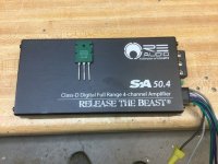
A 100 honest watt per channel class D car amp (100x2 in bridge) isn’t much bigger than a couple packs of cigaretttes. Power transistor for scale. Will murder many plate amps, and can power off a gel cell. Internal supply is about 34V, so 32 can go quite a ways.
Attachments
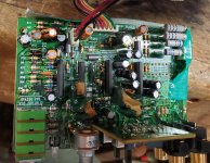
Well, college is starting soon, so my loaner Nobsound G2 Amplifier has to be returned. I looked at the malfunctioning SPA250 and it seemed to operate fine at full power into an 8 Ohm. Temperature was a suspected contributor. The rear cover was installed and after thirty minutes the problem was evident on the output. The positive portion of the sine wave was drooping. This was traced back to the power rectifier P/N RS803. Something went hinky in the positive portion of the bridge. Note: this is a 200V, 8 Amp device. If you work out the current into a 4Ω Load at full power, there is cause for concern. The load will draw 7.9 Amps and that does not leave much margin. I placed a 10 Amp bridge, GBU1004, on order through Digi-Key. This should be a drop-in replacement SIL outline. 10 Amps seems to be the max for this package. There may very well be other problems- the main filter capacitor is suspect. Good listening- EVMan
Attachments
Using a chassis mount 25 or 35 Amp Rectifier is not a bad idea and I considered this. The Bridge rectifier would probably last forever, but a Few factors influenced my decision not to go this route. A new hole would need to be drilled and tapped. Max current or anything close is not required in my application. Max current at 4 Ohms is not a consideration for my 8 Ohm sub. Max current at 10 Watts @ 8 Ohms is a shade over 1 Amp. 10W into a 97db 1W/1M sensitivity woofer is extremely loud, bordering on uncomfortable. I can't imagine playing the sub at 100W and being in the same room. Your mileage may vary. Inefficient subs e.g. 87 dB would need 100W to reach the same SPL of 107 dB and would obviously draw more current. In my case, a 10 Amp bridge is plenty. Still, a chassis mounted, Hi V/Hi I, bridge rectifier might be the way to go for people that drive the amp hard. My two cents. Cheers- EVMan.
Hello EV Man. You wrote "Just finished reviewing the schematics and photographs that were posted in this thread"
Can you please direct me to the post that had the schematics? I have a SPA250 that suddenly started humming LOUDLY one-night last week.
I haven't been able to find any useful info on root causes only sad stories on how unhelpful Dayton is. Ive read through this blog but I don't have any visual symptoms that would indicate a failure mode. I haven't hooked up the o'scope yet just trying to get documentation before I get into the weeds.
Thanks for your Help
JSMREM
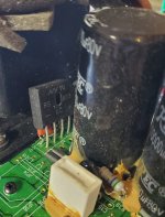
These were the two schematics. The super sub schematic is accurate, the preamp schematic is different, but similar. Most of the pictures' were of the standby and preamp boards The Standby board shows the buckled electrolytic cap near the Molex connector and 12 V Relay. This 470 uF cap has gone bad in multiple instances. It should be a high frequency, Low ESR switch mode capacitor rated for 25 Vdc. Good luck!
Attachments
Finally resuming this project after a crazy summer....
Moving forward with my "hack in a class D module to the dayton plate amp".
I am about to bench test the IRS2092 amp board and read @EVMan had posted about having wrong gain resistors (R11 and R13?)
I tried google searching a bit but came up empty handed.
My board currently has the following values:
R11 = 10K
R13 = 100
If these are wrong, my next questions would be:
1) What values SHOULD these be?
2) Must I replace these with another SMD, or can I use normal through-hole resistors?
3) Expanding on the second question, I am specifically worried that re-locating R11 (in the case of using through-hole) may cause some strange inductance issue. I notice that resistor is just a few mm from the chip.
I found this on another post (re-posting here):
So...
For R13, change the R100 out for a 3.01k for less gain on R13 (seems easy)
For R11, change out the 10K for a 8.2k (which also changes the clock frequency?)
Given my application (the retrofit), is the above correct?
-Dean
Moving forward with my "hack in a class D module to the dayton plate amp".
I am about to bench test the IRS2092 amp board and read @EVMan had posted about having wrong gain resistors (R11 and R13?)
I tried google searching a bit but came up empty handed.
My board currently has the following values:
R11 = 10K
R13 = 100
If these are wrong, my next questions would be:
1) What values SHOULD these be?
2) Must I replace these with another SMD, or can I use normal through-hole resistors?
3) Expanding on the second question, I am specifically worried that re-locating R11 (in the case of using through-hole) may cause some strange inductance issue. I notice that resistor is just a few mm from the chip.
I found this on another post (re-posting here):
R13 from 100Ω to 3.01K Ω for lower gain
R11 to 8.2K Ω for symmetrical current limiting
Adjust clock frequency to 400 kHz
So...
For R13, change the R100 out for a 3.01k for less gain on R13 (seems easy)
For R11, change out the 10K for a 8.2k (which also changes the clock frequency?)
Given my application (the retrofit), is the above correct?
-Dean
Last edited:
Hi Dean,
How are you? And thanks for the question . . . You are correct about this being a crazy summer. My project progressed well up to my wife’s sickness. My apologies to all. My IRS AMP500 board had both resistors as you indicated. Into a resistive load, the audio gain was way too high and will likely oscillate into a reactive load. Changing R13 is mandatory for stable operation. A value of 3K -4K Ω will allow for proper operation (Gain-wise). However, the low value of R13 creates possible drive problems for the preceding stage(s). For example, my Yamaha RX-V667 had trouble driving a 3K Ω load.
R11 change to 8.2K Ω sets the current limiting symmetry. I did not test this out and from my reading it seems this is an issue at high power levels. My little amp has been run up on the bench sans a preamp. Since Class D Amps use some critical path runs, SMD Components were retained. Tough to work with- I had to break out the Pace Station. The surface mount components are very inexpensive. Matter of fact, it is getting harder to find thru-hole components.
I do have the components on hand for a simple preamp/attenuator/18 Hz HPF and the attached PDF Sketch depicts this simple circuit (minus power supply). The power supply unit (PSU) is a simple resistor-Zener-cap-Darlington combination that generates ± 15 Vdc. This power supply/preamp circuitry is all that is left to finish the project. These two circuits have not been built or tested. Cheers- EV Man
Attachments
Thanks for the info, I will update another thread I started regarding this IRS2092 accordingly. Don't wanna hijack this thread.
Yeah... It is not so much a cost thing regarding SMD, but the skill aspect. I have little tooling or skill/experience working with SMD. That said... Seems the resistor that NEEDS to be changed is both easy to access/replace with traditional one and... It is in a place where an extra 3-4mm of leads should not affect anything.
Regarding the R11, I will not be using this in any high power capacity. In fact, I will be operating this on it's low end.
These will power a couple LARGE vented subs with old Dayton Classic 15s (150 watts will be enough to drive the cone past Xmax at the lower limits).
I will begin bench testing the new IRS2092 boards this week and testing the gain accordingly. These will be driven with the original Dayton pre amps, so let's see how that works.
Hi Dean,
My apologies for missing your SMD soldering skill input. My experience includes AMRIP micro-miniature repair x 6 weeks (NASA Approved repair course for space craft). That was 45 years ago- I think they were still launching Apollo Missions back then. Back on track . . . Times and technology march forward. The only surface mount devices we used back then were “flat packs” that used conventional solder. Almost everything back then was ‘plated through hole’ or tubes. There were no cell phones. Cell phones exist now in large part due to surface mount technology. Aside from the miniaturization of the components, the big change was to ‘lead-free’ solder. My experience was limited to the last year of work and by that time, I had been demoted to management. I do remember that ‘lead-free’ solder has a higher meting point than conventional lead based, eutectic 63/37 solder.
I would be interested to hear of your soldering/repair experience with this board. I used a pair of flush cutters to snap the resistor’s ceramic body in half. The body crumbled and this left a solder tab on each end. These came right off and the replacement was ‘hot gas reflowed’ to bond with the traces. A $3000 Pace Station was used, but you can get good results with a regular soldering iron. I only messed with the input gain resistor. The end result was acceptable. I only mention this because of the higher melting point of lead-free solder; it is much easier to lift traces if this factor is unknown. Good luck. EVMan
- Home
- Loudspeakers
- Subwoofers
- Dayton SPA250 Plate Amplifier repair help