Voltages Outputstage
Some help appreciated..
I have been running the old DAC END 2 for some time now with E182CC. Since on the one hand Quanquaho had swapped to 6n6h later and on teh other hand my Mullards E182CC are rather microphonic I configured my second outputsage PCB with 6n6h (after reworking the PCB).
I did it after the Quanquaho circuit design.
Anode Resistor: 3K (6x18K)
Kathode Resistor: 400 R
B+: 270 V
HV Shunt runs at 82mA
In this configuration I get about 180 V plate voltage and 6.1V kathode voltage.
Each triode system runs on 15mA.
Asking the datasheet it says, that the tube should run at 120 V Vplate. And here I found it runs good at about 18mA each triode system. More current would let come down the Vplate. So what to modify to get there?
Thanks for your help.
Ernst
Dac End vs AN board sonics
With the incredible help of Strosek the Dac End is working and in the circuit that used to have the Audio Note board in it.
The cleaner power offers better separation which I was hoping for when I decided to replace the AN board with this one.
It only has about 35 hours on it but its a colder presentation with less body and dynamics than the audio note board. I don't know if this is due to the characteristics of the power supply or the slight different way the 1865 is being utilized.
I recall another member mentioned something like this. Since I literally just replaced the AN board with this one its really a good comparison.
Maybe the power supply and transformer need more hours? Not sure. I know 100 hours is about right for caps and such.
I played around with the HV Shunt and found some significant upgrades, at least in my system.
First one was a 22µF film cap for the second filter cap after the 470R resistor-better dynamics, clarity and separation. Then, maybe even more important, was a choke instead of that resistor, which brought out even more dynamics and stability, but also more colours and naturalness. I had these parts in the drawer, so no extra cost...
Then the 1µf caps are also critical, one can try a good 0,1µf bypass cap.
And I did not try a tube rectifier, the solid state diodes should add some solid state sound as well.
Reading your post again it seems you mean the dac-board itself..lol
O.K, I still do recommend those changes to everybody who is using the Dac-end output stage.
Regarding the Dac-board: do you have the TL431 installed, or do you feed directly with the shunt? And then, in my experience, it takes more than 100 hours to sound as it should, when all the parts are new.
And maybe it is just different...
Regarding the Dac-board: do you have the TL431 installed, or do you feed directly with the shunt? And then, in my experience, it takes more than 100 hours to sound as it should, when all the parts are new.
And maybe it is just different...
I feed direct with the shunt as per the single board that includes the shunt supply. I don't see the TL431 anywhere on the schematics.
Also I should add the only change I made was the value of the input caps. Several digital designers I know and respect said they found that .1uF was much better than .01uF as input caps in a dac. The cap on digital input pin 9 of the 1865 has a 47uF on it. The AN schematic calls for a 100uF and I even went to a 220uF at that position (black gate) on the suggestion by the same person and it sounded better although the cap it was replacing wasn't as high quality.
Last edited:
Grounding
Pharod,
From a total different DAC I have in mind, grounding is a big issue. Digital and analogue ground should be separated strictly for optimal result! In the DAC ASHs predecessor, the DAC END 2 which is my current DAC, I found suboptimal grounding scheme. I haven't done a DAC ASH grounding analysis, but I can imagine, that Quanghao just copy pasted the layout for his new pcb.....
Clarity and stage might improve.....
...just an idea....
Cheers Ernst
With the incredible help of Strosek the Dac End is working and in the circuit that used to have the Audio Note board in it.
The cleaner power offers better separation which I was hoping for when I decided to replace the AN board with this one.
It only has about 35 hours on it but its a colder presentation with less body and dynamics than the audio note board. I don't know if this is due to the characteristics of the power supply or the slight different way the 1865 is being utilized.
I recall another member mentioned something like this. Since I literally just replaced the AN board with this one its really a good comparison.
Maybe the power supply and transformer need more hours? Not sure. I know 100 hours is about right for caps and such.
Have you retained the Audio Note I/V resistor values? If not it is well worth doing this and testing again.
Pharod,
From a total different DAC I have in mind, grounding is a big issue. Digital and analogue ground should be separated strictly for optimal result! In the DAC ASHs predecessor, the DAC END 2 which is my current DAC, I found suboptimal grounding scheme. I haven't done a DAC ASH grounding analysis, but I can imagine, that Quanghao just copy pasted the layout for his new pcb.....
Clarity and stage might improve.....
...just an idea....
Cheers Ernst
Hi!
Please Sent to me an idea!
Thanks
Pharod,
From a total different DAC I have in mind, grounding is a big issue. Digital and analogue ground should be separated strictly for optimal result! In the DAC ASHs predecessor, the DAC END 2 which is my current DAC, I found suboptimal grounding scheme. I haven't done a DAC ASH grounding analysis, but I can imagine, that Quanghao just copy pasted the layout for his new pcb.....
Clarity and stage might improve.....
...just an idea....
Cheers Ernst
Basicaly the ground/power supply for digital units should be separated to analog units (in AC point of view). We can found this importance note in AD1865 data sheet page 6 [AD1865–Analog Circuit Consideration]
In DC point of view we can connect two part of digital unit and analog unit by suitable choke.
Just for you and Hao reference in future pcb layout
")
Keep up the good work people!!!!
Basicaly the ground/power supply for digital units should be separated to analog units (in AC point of view). We can found this importance note in AD1865 data sheet page 6 [AD1865–Analog Circuit Consideration]
In DC point of view we can connect two part of digital unit and analog unit by suitable choke.
Just for you and Hao reference in future pcb layout
Keep up the good work people!!!!
Sometimes the datasheets get it a bit wrong. Another view is that a single uninterrupted groundplane & proper partitioning / layout are the way to go. Please take a look at:
ADC Grounding
The Extremist DAC
To improve performance of the DAC you might want to mount the 3 chips deadbug style on a solid sheet of copper with proper decoupling & keeping digital & analogue partitioned rather than split. With the PCB allowing for 6x galvanically isolated power supplies there is no problem here!
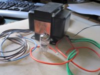
HELP with Tube stage required Please
As this is my first tube project I find myself pulling my hair out and at this point I could really use some help...PLS
Talking about the tube stage here are the numbers:
Input Voltage: 235VAC Buds transformer
R1 2.9V - 26R
R10 265V - 47R
R11 29.5V - 470+450 = approx 240R
+HV with jumper to +B = 83V
R20 83.5V
R24,R23,R28,R27,R22,R21,R26,R25,R29,R30 = No Voltage!
Filement Side +F jumpered to 6.3V = 6.3 Volts
Tube used is a 6H30
Does the board require any other jumpers? ie:upper left side of board?
If someone could review these numbers and tell me if they look OK or not before I install the tubes it would be greatly appreciated.
Thanks!
No relies... WOW... Well now that I've fixed everything and the DAC and Tube stage are both working hopefully I'll get some replies
Ok, here are the numbers:
B+ = 200V
R1 = 2.5V and 23.7R
R11= 25V and 230R
R22 3.8V and 196R
Anode 87.5V
Filament 6.3V
All measurements taken while running with tubes in.
Are these values optimum for my tubes? Do I need to make any changes to anything?
The sound is pretty good but I find that I'm lacking in gain and dynamics. Using my passive pre amp I'm at full volume and it's not loud at all...
When I connect it to an active Pre amp and boost the treble and bass a bit it sounds quite good but I have a feeling that something else is going on and don't want to put a Band-Aid on a problem.
I would GREATLY appreciate some assistance
Thanks!
Last edited:
No relies... WOW... Well now that I've fixed everything and the DAC and Tube stage are both working hopefully I'll get some replies
Ok, here are the numbers:
B+ = 200V
R1 = 2.5V and 23.7R
R11= 25V and 230R
R22 3.8V and 196R
Anode 87.5V
Filament 6.3V
R1 = 2.5V and 23.7R
It is ok ~100mA total curent!
So better Anode 90V, the sound is good, and 20mA for 1/2Tube 6H30!
No! you can use trimer get +B to 205 or 210, get 40mA for on tube!
Thanks
Some things gone wrong
Hi My dac2 has been working fine and am very impressed with the sound ,i have used it with the Shigaclone transport together they are fantastic .
I used it last night but switching on today my r80-36 makes a buzzing sound and r11 (5w) is red hot and would smoke if i did not swich off ,,Any help please regards john
Last edited:
I would check the transformer first, if it is working without load. But I think a transistor went south in the HV shunt. I experienced this 2 times due to a short, and in both cases replacing the transistors fixed it. Replace them all at once, it doesn't cost a fortune...that is the 2sk170, IRF740 and 9610.
Good luck, and yes, it sounds fabulous after fine tuning...
Good luck, and yes, it sounds fabulous after fine tuning...
Hi My dac2 has been working fine and am very impressed with the sound ,i have used it with the Shigaclone transport together they are fantastic .
I used it last night but switching on today my r80-36 makes a buzzing sound and r11 (5w) is red hot and would smoke if i did not swich off ,,Any help please regards john
Hi! you can down R 11 !
EX: 100 - 470R
If use 100-200R, only 5W
If use 470R , so paralle 1K/5W
It is no hot!
Thanks!
I would check the transformer first, if it is working without load. But I think a transistor went south in the HV shunt. I experienced this 2 times due to a short, and in both cases replacing the transistors fixed it. Replace them all at once, it doesn't cost a fortune...that is the 2sk170, IRF740 and 9610.
Good luck, and yes, it sounds fabulous after fine tuning...
Jogi Thanks,,, you are correct transistors blown ,frustrating but its working again,i have kept some spares in case there is a next time regards john
- Status
- This old topic is closed. If you want to reopen this topic, contact a moderator using the "Report Post" button.
- Home
- More Vendors...
- Quanghao Audio Design
- DAC-ASH (dac-end 2 up date)