Hi Spencer, are you saying that first order filter is good enough for the PCM63 with the DF1704?
Anyway, I will be getting promitheus D1 pcbs. When I have the time, I will try to build the I/V stage based on your design. I have managed to source for the necessary parts though it was not easy.
If it is convenient, drop me an email. Thanks.
Anyway, I will be getting promitheus D1 pcbs. When I have the time, I will try to build the I/V stage based on your design. I have managed to source for the necessary parts though it was not easy.
If it is convenient, drop me an email. Thanks.
They are going for about 30 cents each.
Actually, I was thinking that it would be good to set up a JFET barter trading portal where forumers can trade JFETs for others with the right Idss values for their applications.
This way, it will help avoid hoarding behaviours for out of production JFETs like 2SK389
Actually, I was thinking that it would be good to set up a JFET barter trading portal where forumers can trade JFETs for others with the right Idss values for their applications.
This way, it will help avoid hoarding behaviours for out of production JFETs like 2SK389
D1 Problem.....
Finished a D1 I/V stage made on lab board a couple of days ago, and i find that I cannot adjust the source voltage sufficient using the 20K trimpot - the channels starts out around -3.3 volts, and I can adjust them to -835mV and -1015mV - and here they are stable to around +/- 1 or 2milivolts - that should be okay ? apart from beeing to much
Can it be an error ? how do I check the correct function of the I/V converter ? sending audio through it ? Should I use another value for trimpot ??
Cheers !
Buhl
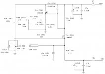
Buhl said:Can I check it sending an ordinary line level signal through it and on to an poweramp ?
I don't think that will be wise. The circuit needs a current input in the 4mA range, I guess that a line level would sound horrible and it doesn't really test if your configuration works. You could end up burning your speakers.
You could try to lower the value of R5. I used a 47k when I had to set the input to 2.5V. If you still cannot get it to 0V, my best guess is that something is wired incorrectly or you might have some wrong resistor values. What are your rail voltages and on both sides of R1 and R7?
cviller said:
I don't think that will be wise. The circuit needs a current input in the 4mA range, I guess that a line level would sound horrible and it doesn't really test if your configuration works. You could end up burning your speakers.
You could try to lower the value of R5. I used a 47k when I had to set the input to 2.5V. If you still cannot get it to 0V, my best guess is that something is wired incorrectly or you might have some wrong resistor values. What are your rail voltages and on both sides of R1 and R7?
Hej Cviller !
All resistor values are as in the schematic, and my rail voltages are +/-29 volts. I will try 47K@R5 ! (and run the circuit over for errors again....)
Thnx for helping out !
Cheers !
Hans
Just a quick one before I power up -It may sound silly, but should the gound plane on the dac board not be connected to the ground on my D1 I/V board ?? and shold a resistor be placed between the two grounds ??
Cheers !
Hans - who is only a wire from sweet sounds....hopefully ;-)
Cheers !
Hans - who is only a wire from sweet sounds....hopefully ;-)
- Status
- This old topic is closed. If you want to reopen this topic, contact a moderator using the "Report Post" button.
- Home
- Amplifiers
- Pass Labs
- D1 I/V Stage Finished.