Continuing about replacement Inductors for 44
I received a request from a member which I Copied and Pasted here-below and will reply to here ,
because it is relevant to this thread , following earlier discussion about replacement Inductors earlier in this thread.
I recommend all owners of 44s who are upgrading the Inductors proceed as below the ***** enclosed insert:-
*****
" 44 Bass X-over inductor upgrade.
Alan, for my 44 TBC bass section, I am looking to replace the iron core inductors with air core in the values 3.3mH and 2.0mH.
I can't afford the very lowest DCR inductors, and nor do I imagine that they are really necessary.
Would 1mm wire be sufficient to yield a major improvement in your opinion?
That would produce 3.3mH with 1.04 Ohms and 2.0mH with 0.8 Ohms.
The ones I'm looking at are Jantzens, like all of the caps in my crossover (your advice I believe! )
__________________
Lucas "
*****
'ullo Lucas ,
I strongly recommend you do not buy the 1mm wire Inductors , nor even buy the wire and wind them yourself ,
because you will be wasting your limited money.
The original Ferrite cored inductors are significantly lower DCR than the new ones you propose ,
thus whatever audible gains you achieve with less Saturation with the Air-cores ,
will be offset by loss of output level and Transient Response as result of the significantly higher DCR of the Air-cores you propose for the WOOFER filter.
I refer you to kayelem's measurements in the File attached to #143 on Page 15 of this thread ,
and remember that these resistances are with respect to the 4 ohm Woofer ,
that you propose to add almost 3 ohms in Series with !
I refer you also to rwtomkins attachment of the original Celestion data in #188 on Page 19 of this thread.
See there the difference between the two versions of 44 for both L2 in Midrange and L5 in Woofer circuits.
As you have 30uF for the Midrange input capacitor I recommend you use 2.2mH for L5 to the Woofer for a more even crossover transformation.
To get the best from the Woofer with the Jantzen inductors I recommend:-
000-0034 , 3.3mH , AWG14 , 1.6mm , 0.482 ohm ,
000--0028 , 2.2mH , AWG14 , 1.6mm , 0.385 ohm.
If you absolutely will not buy those large sizes , then buy not smaller than:-
000-1199 , 3.3mH , AWG15 , 1.4mm , 0.615 ohm ,
000-1246 , 2.2mH , AWG15 , 1.4mm , .473 ohm ,
or :- 000-1338 , 2.1mH AWG15 , 1.4mm , 0.46 ohm.
Where you can save money is for L2 in the Mids' filter ,
because some resistance is useful there as it reduces the onset and magnitude of Resonance within the mids' filter itself.
This will not reduce output level , it will increase clarity/transparency.
For that inductor I recommend any of:-
000-1697 , 2.1mH , 21AWG , 0.7mm , 1.36 ohm ,
000-1255 , 2.1mH , 20AWG , 0.8mm , 1.2 ohm ,
000-1355 , 2.2mH , 21AWG , 0.7mm , 1.38 ohm ,
000-1564 , 2.2mH , 20AWG , 0.8mm , 1.23 ohm.
Which is closest to optimum ?
I do not know , however I would start with the 2.2mH at 1.23 ohm ,
as that will cause the smoothest roll-off to the filter , particually as you have 30uF acting with it ,
but if you have to cut costs here to enable better inductors for the Woofer filter , then buy 2.1mH in whichever version the local seller has.
Also , for the UK seller , I recommend very much that you do not follow his advice on any choice of components ,
because he has very badly advised at least two members of this Forum and ruined their Celestion 66s ,
and he will not accept any responsibility nor refund nor exchange the incorrect parts for more suitable ones.
He does not understand how passive crossover components interact with the reactive Impedance of the speaker drivers ,
regardless of having a Computer Program , because he does not know how to instruct it with regard to real-world drivers' behavior.
With these physically larger inductors than the ferrite-cored originals , where they are placed on the board in relation to each other is critical ,
because their magnetic fields will interact with each other and thereby reduce some of their otherwise audible benefits.
Ideally you should make a new board of not less than 10.5 inch square ,
or 11 inch x 10 inch for all the components ,
or use the old board for Mids and Tweeter , and make a new 10.5 x 5 inch board for the Woofer filter , and position it a little away from the old board.
I will comment more about placement after you have bought inductors and are ready to start.
I recommend strongly that you continue to save money until you can afford the low DCR inductors.
The 0.66mH and 0.14mH Celestion originals are Air-core , and thus do not need replacing if not damaged.
***
Hey , please update us on what capacitor values you now have in your Tweeter filter ...
... is it still 3.9uF and 10uF ?
Last edited:
There is a mistake in my post above.
Where I stated "almost 3 ohms":-
I should have stated:- "almost 2 ohms in Series with"
2 ohms in Series with a 4 ohm woofer still causes significant loss.
Ideally there should be no more than 10% of the Impedance of a Woofer in Series with it , including the resistance of the loudspeaker cable ,
which is this case would be only 0.4 ohm maximum for cable plus inductors.
That will be impossible the Celestion 44 , however let us keep the Series resistance as low as possible , thus my advice about the inductors in the above post.
The remainder of my post is correct ... I hope !
Where I stated "almost 3 ohms":-
I refer you to kayelem's measurements in the File attached to #143 on Page 15 of this thread ,
and remember that these resistances are with respect to the 4 ohm Woofer ,
that you propose to add almost 3 ohms in Series with !
I should have stated:- "almost 2 ohms in Series with"
2 ohms in Series with a 4 ohm woofer still causes significant loss.
Ideally there should be no more than 10% of the Impedance of a Woofer in Series with it , including the resistance of the loudspeaker cable ,
which is this case would be only 0.4 ohm maximum for cable plus inductors.
That will be impossible the Celestion 44 , however let us keep the Series resistance as low as possible , thus my advice about the inductors in the above post.
The remainder of my post is correct ... I hope !

£200 for an inductor upgrade!!! That's more than I can stomach for a few coils.
I think I'm going P-core! I hear they saturate less than iron core. Wadya think?
I have read many reports that you'd have to get them to stupid volume levels before they saturate, and you can get them in lower DC resistance than the originals (or indeed air-core) meaning less attenuation and a higher bass output (if so desired). I personally would aim for around 0.3Ohm and 0.5Ohm, rather than the really low DCR ones, as I think straying too far from the 0.5R and 0.7R of the originals could off balance the driver outputs more than I'd like. I think the slightly higher output would be good for me. I imagine that Celestion chose to introduce some DCR here with the coils to attenuate the driver and balance the sound, as opposed to adding a resistor.
Last edited:
Mundorf M-coil Air-core ; P-core ; DIY-core
'ullo Lucas ,
I think the 200 you stated includes the 14AWG options for the Woofer section ,
as the 15AWG versions will cost less , but I suppose still too high price for you ...
I had forgotten about Mundorf M-coils , probably because they do not offer a 3.5mH ,
and I had done the Inductors research for the Celestion 66 , which requires 3.5mH.
Mundorf M-coils are available in several types , including Air-core.
I advise you consider the following:
BL140 , 3.3mH , 0.58 ohm @ 25.55 , is 15AWG , 1.4mm wire ;
BL140 , 2.2mH , 0.46 ohm @ 19.59 ; is as above ;
BL71 , 2.2mH , 1.39 ohm @ 8.53 - for the Midrange circuit is 21AWG , 0.71mm wire .
So Total price is only slightly more than half the cost of the Jantzen option you priced.
Mundorf are sold in the UK by Hi-Fi Collective , at:
amplifier valve kits, HIFI pre-amplifiers, speaker kits,AMP Parts, upgrade components
There are two price lists there for the inductors , one with no VAT and other is with VAT.
I listed the with VAT prices here-above.
The next Mundorf in thickness is 2mm wire , but is similar price to the Jantzen 14AWG you prefer to not spend on.
The BL Mundorf is the Baked Varnish option.
I strongly advise you buy this option at its slightly higher price than the non-baked L versions -{ L140 and L71 }- ,
because the non-baked coils will vibrate and thus cause audible resonance through the speakers ,
and especially audible with the midrange coil !
The audible resonance is from the modulating magnetic field caused by the wire vibrating within the coil becoming electrical signal in the circuit.
I cannot recommend the Jantzen P-core , because I have not used them and listened to the result.
If you insist on buying P-core , then buy in the lowest DCR you can afford ,
and no higher than their 15AWG options for the woofer filter ,
because Solid-cored inductors do not behave like Air-cored inductors.
Any metal solid core will heat up whilst the music signal current is flowing , and that heated core will cause Saturation.
This P-core Permite may not saturate to the degree that Ferrite does , but it will to some degree.
Keep the DCR of the wire as low as possible to keep the wire as cool as possible for ALL metal or metal particle or metal oxide cored inductors.
Heat is much less of a problem in the wire of Air-cored inductors.
I see the lowest DCR P-cores cost similar to the BL140 versions of the Mundorf M-coil Aircores ,
so I recommend the Mundorfs despite their higher DCR , because they will saturate less.
Perhaps the P-cores in lowest DCR options will produce as good sound with the old Celestion woofer ,
if the limiting factor happens to be Saturation in the woofer's pole-piece.
If the woofer's magnetic circuit is saturating to a significantly larger degree than the filter inductors' circuit , then type of inductor is not critical ,
however those old Ferrite cored inductors in the Celestion 44 do saturate to quite audible effect.
The P-core Jantzens will not saturate as much , but whether they will not before the woofer does I do not know.
The DCR of Celestion's Ferrite inductors would have been result of the Budget allocated to cost of the inductors , and not to attenuate the signal level.
Celestion would have had no reason to want to attenuate signal to the woofers of the 44 ,
as it was intended to be an efficient loudspeaker for the input signal levels.
If you buy P-core at your own risk/experiment for the woofer filter ,
I strongly recommend you do not for the midrange filter.
Buy the Jantzen air-core with its medium DCR for the mids , because core saturation is more audible in the midrange than in the bass.
Also , if you buy the P-cores for the Woofer filter , buy the options without the end Discs ,
because the Discs being more core will cause more saturation.
The addition of the end Discs is to lower cost , because that core material costs less than copper wire.
DIY is what this Forum is about ,
so you could wind your own inductors ...
and if you have not previously done such , then I advise you try with 20AWG 0.8mm wire and wind the midrange inductor to find out how you manage ,
because winding with the thicker wire for the woofer filter inductors is difficult , so better is to experiment and find out what you can do.
If you decide to wind your own , then Post here first and I will give you some tips on how to get the best results.
Magnetic Hysteresis ; Crossover Board/s
'ullo Lucas ,
As far as I know to date , Mundorf do not actually manufacture all , or perhaps any , of the components they sell ,
but have them made by various Companies which apply Mundorf's particular Specifications and design ideas to the standard products those companies otherwise manufacture.
Thus the Price varies between high and not-so-high dependent on the cost of implementing the various design ideas and specifications into whatever Scale of Production.
More about Air versus other Cores for Inductors:
All core types that increase the inductance of a coil have other properties than only saturation.
In particular , Search and read about Magnetic Hysteresis ,
and the related: Remanence ; Retentivity ; Coercivity.
Hysteresis means Lagging.
The effect in Magnetic materials in Audio terms is similar to the effect of Dielectric Hysteresis in Capacitors ,
more commonly known as Dielectric Absorption - which I have posted about previously.
The P-cored inductors may not saturate at as low signal levels as Ferrite cores ,
but will still have the Hysteresis "lagging" effect on the signal to some degree.
In circuits where both Electrolytic caps and Cored inductors are used together ,
such as in many , and perhaps all , KEF's crossovers for ALL the filters -tweeter ; midrange ; woofer ;
there will be an homogenous effect throughout the audio spectrum which sounds balanced even though not timbre accurate ,
because the entire sound will be "lagged".
Some listeners like that sound.
Audible problems occur when some "lag" sound components are used with some closer to timbre transparent sound components ,
because then the resultant Colourations caused by the "lag" sound components are only in parts of the Audio Spectrum whilst the sound is clearer in other parts of the Audio Spectrum.
Usually Human hearing tolerates tonal Balance better than tonal un-balance.
Thus I think why when good Audio quality Polypropylene caps and low-microphonic varnish baked { or similar } Air-Core inductors are used in part of a crossover ,
the result is audibly better when the same are used in all of the crossover ...
... even when not in the preceding Amplifier , because that is a different stage in the signal path.
Keep a similar type of sound signature in each stage , and then there is hope for better Balance throughout the chain.
If you follow the Celestion 66 midrange Thread currently ,
you will read the reports by "reggie" following the inclusion of low DCR Air-core Inductors in his new crossover.
He has encountered another problem we have yet to solve ,
and that may include how he has connected the new Inductors ,
so wait till we find the cause before you connect anything.
The old Celestion crossover boards are too small to fit 5 inductors without excess crosstalk/coupling.
I recommend you either make a new much larger board , as I posted minimum dimensions for recently in the 66 Thread ,
or use the old board for tweeter and midrange filters , and make a new board for the woofer filter to put the new inductors and capacitors onto.
The new 2.2mH midrange Inductor can then be placed on the old board further distant from the two existing Air-Cores ,
and simply have its leads connected to the circuit points where the old cored 2.0mH was connected.
I will post more about spacing and layout later -
- first read my Post about such in the 66 thread , in #1022 on Page 103 here:
http://www.diyaudio.com/forums/multi-way/93055-celestion-66-needs-mid-range-103.html
and then decide whether to use 1 or 2 boards ,
and post your preference here.
P.S. - I agree with you in the 66 Thread about Silver loaded solder.
It is practical only for Silver-Contact surfaces.
I posted a bit more about it at the end of my #1029 in the 66 Thread.
Last edited:
My 44's and their crossover upgrade
Hi All,
I found this thread a few months ago after acquiring a a pair of Ditton 44's off EBay. My intention was to use the 44's as a backup for my existing Ditton 66's and as a supply of some of the drivers for the 66's should any fail. I also wanted to see what I would need to upgrade in the 44's to get them to perform at their best.
I have also read all the "Ditton 66 needs mid-range" thread and the "Custom Ditton Project - need expert opinions" thread.
I think the depth of knowledge and the help given to Ditton 44 and 66 owners on how to upgrade their speakers by some of the main thread contributors has been oustanding. I can only thank them for all the work and help they have put into this forum that has permitted me a relatively easy path to upgrading my 44's.
I hope to add a little to the overall knowledge base on upgrading Ditton 44's and 66's based on my recent upgrades to my Ditton's which has been based primarily on the information in these threads.
Celestion Ditton 44's were my first set of non-DIY speaker's in 1975 after completing a Electronic Eng degree. After much auditioning along Tottenham Court Rd listening to B&W's, IMF's, JBL's KEF's etc I was blown away by listening to Celestion Ditton 66's. I couldn't afford those unfortunately but ended up buying Ditton 44's.
I moved with my job to Ipswich around 1976 and via a colleague, whose sister worked at the Celestion factory, got a set of factory Ditton 66 "seconds" (a small imperfection in the veneer) for a real knock down price easily recouped by selling my 44's. The 66's have stayed with me since then. The only problem I have was a blown HF2000 when my home built amp blew its outut transistors in one channel. Got a factory reconditioned replacement for the princely sum of £8.50.
Anyway sorry about the diversion and back to my 44's and their upgrade. Having read and re-read all the threads my 44's are the "blackie" versions and on opening them up one had the manufacture date stamped inside under the crossover: 24th September 1974. This speaker has had its mid-driver remounted 45% round...not sure why and I havn't investigated further as its working fine and the job seems well done with the old mounting holes well filled in, levelled and painted. The other speaker is "standard" but didn't have a date inside.
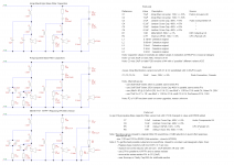
Both crossovers are the TBC type with one seemingly having what I call 1st generation capacitors and the other having what I'd call 2nd generation capacitors. The earlier generation capacators measure far more out of specification that the 2nd generation (altough I am somewhat mistrustfull of my meters readings on eletctrolytic capacitors values. All the driver units are in very good condition and have no obvious of discerable damage. See the attached PDF files for details of the unmodified speakers.
As with others findings, Celestion seem to have changed capacitor values "at will" probably depending on either supplier or cost (or both) preferences. Speaker 1 crossover uses 2uF caps to make up the treble filter caps of 4uF and 6uF values whereas Speaker 2 uses 2.2uF caps ending up with 4.4uF and 6.6uF...go figure !
I suppose it possible my speakers are not an original pair but externally they certainly match or someone could have replaced a whole crossover but I can't see why.
I found so much information on possible crossover upgrades in the threads that I attempted to put together a single short document that shows most of the pertinant design information and possible variants. I decided on a 2 stage upgrade for the following reasons:
(i) to allow me to try to hear the difference that has been much discussed between polypropylene metal film and electrolytic capacitors by using new electrolytic bipolars for the bass filter.
(ii) to assess the real costs and sutability of Axon polypropulems from Part Connexion (by far the cheapest option for bass cap filters) by uing them on my Ditton 66's upgrades first.
(iii) to get the 44's done quickly/cheaply so I could use them whist upgrading the 66's with supposidly "better" caps which I could then compare against (perhaps not entirely a fair comparison but nethertheless "interesting" in my view.
My plan for upgrade components was to source them as cost effectivly as possible as a UK based buyer bearing in mind additional P&P/handling costs for multiple sourcing. I also didn't particularly want to build new crossover boards at this point in the upgrade process as I would be using the standard Celestion inductors and main internal wiring (as has been pointed out several times it's actually quite good quality).
I put together a spreadsheet for and populated with possible options and prices from diferent suppliers for a 44 upgrade using low to mid-range capacitors mentioned throughout this and the 66 thread (my 66's would be treated to the better components as they would continue as my main speakers). I also looked at a number of capacitor comparison sites where the caps were being used in crossovers....I am somewhat sceptical about these as inevitably the more "expensive" win and the costs are just mind boggling. I really can't believe the differences they claim they are hearing.
In the end, I bought the components for my stage 1 upgrade from 4 main sources (some of which were also used for the 66 components so sharing costs and minimum order quatities).
I decided on Jentzen Cross Caps for the mid and treble parts of the crossover and Alcap bipolars for the bass. Resistors were by preference Welwyn WPS 4W where I caould get the value required and Mills MRA5 otherwise. Suppliers used are shown in the attached upgraded crossover PDF file.
I also show the Axon bass caps intended for my 66 crossovers layed on the Stage 1 upgraded 44 board, showing that they will easily fit with some some bass inductor moves on the existing crossover board.
In my upgrade design variants I also looked at what required to replace the HF2000's with a SEAS H737 19TFFI1 which seems to be the preferred path should the HP2000's fail. Given the "preferred" capacitor values to use the SEAS with the existing Celestion treble inductor does help steer your initial choice of mid/treble capacitors as I think it's wise to keep them the same make/type for balance.
A note on the suppliers I used. I'd rate then all good on delivery. I choose CPC (ex part of Farnell ?) for the Welwyn resistors as they have no minimum order price unlike Element 14 (also ex Farnell) and free P&P. Have to say I'll be using them again in the future...although they don't have the component range of Element 14.
The total cost of the stage 1 upgrade came in at £68 including speaker binding posts
Stage 2 costs to upgrade the bass filter section have proved to be cheaper than expected based on the 66's with the Axon caps inc. shipping coming in at £47.50 inc P&P which was $20 from Parts Connexion....somehow I didn't get charged any VAT so assume the cost was lower that the threshold for charging VAT on non-EU imports. So going straight to the recommended Stage 2 upgrade will cost £100 into total.
I will be ordering those Axon's in the very near future.....they have proven themselves in the 66's.
Since my purchases I have just found a European supplier "Europe Audio" who stocks all the Jantzen capacitor range at approx half the cost of the UK supplier I bought from. So the costs could have been reduced further or I could have bought Jantzen Standard Z caps at the same price as I paid fro the Cross Cap..."c'est la vie" as they say. Europe Audio have a good range of components/speakers and electronic components and their postage rates are comparible with some UK suppliers. I may try them out in the near future as I am contemplating using Cross Caps for the 44 bass section crossover rather than Axon as the cost will be similar. I'll have to use 33uF/39uF paralled for both 72uF locations. Size is similar to the Axon 36uF's.
Anyone reworking the 44 crossover should note the following:
(i) due to the thickness of the sound absorbing foam and the positioning of the crossover behind the bass driver there is not much scope for using large diameter capacitors or "double dedecking" capacitors without major foam surgery which would lessen damping. The only other feasible crossover location is on the bottom of the cabinet which would mean complete internal cabinet rewiring.
(ii) the 44 crossover seems to be positioned sideways in the cabinet with the "Top" facing the side of the cabinet rather than the top (unlike the 66). This means the drive leads from tweeter and mid drivers have to connect further "down the board". As can be seen from the picture there is minimum slack in the supplied cabling. and its a nightmare to resolder the wires backonto the board. I recommend the input wires are desoldered at the input terminals on the back of the speaker binding posts (which I changed to better types) and the the driver wires are soldered to the crossover board before it is refitted via its screws...this gives some cable slack to work with. Otherwise a complete rewire would be needed.
(iii) I did get some QED Original 42 strand speaker wire (Polyethalene insulation) for internal rewiring but its conductor area is no better than the standard wiring. I also had some QED 79 Original but only enough to rewire the 66 crossover input (its seems way thicker conductor than necessary for the driver connections IMHO given the wiring AWG used on the crossover board and on the component leadouts.
And what about the result ?
I did the upgrade on Speaker 1 first (thats the one with the older type capacitors). The result was a much cleaner and sharper mid and treble with what seems a better balance/transition between the two. I can actually get the treble now whereas before I couldn't really distinguish it.
I have to say the bass has sharpened up too although not to the same degree...no doubt due to the electrolytics.
Overall balance between the three drivers seems good to me. So I saw no need to tweak R1's value in the mid input for example. My choice of a 27uF capacitor for mid C3 seems fine as a half way compromise between 33/30uf and 24uF alternatives given the drive units I have.
Doing speaker 2 didn't bring the same percentage improvement but gave me a balanced pair of speakers with a nicely detailed sound stage. As a whole they sound great IMHO and the more I play them the better they are sounding (some initial harshness on female voicing (Hayley Westenra) for example has no gone into a nice smooth delivery) so perhaps there may be something to the "running in capacitor" story...although without real back to back test its hard to prove.
I can say I don't feel any burning need to replace the HF2000's with Seas 19TFF1's as the treble sounds great to me (but my ears probably can't get much above 12khz on a good day !).
I can't really say whether the Jantzen Cross Caps I used on mid and treble filters are noticable worse than the more expensive ClarityCaps ESA's I used on the 66's as comparing 44's and 66's is not as simple as an "apples vs apples" comparison as both my wife and myself agree. They are just sonically so different subjectively. Heard on their own either the 44's or 66's are great IMHO but do an A - B comparison and the 66's win hands down as far as I'm concerned. I have seen diffent opinions on this forum; all to their own taste I guess.
In the end I will most definitely NOT be using my 44's as a source of spares for my 66's...they really are way too good for that. For the time being I'll keep them and they can act either as my second music system in my DIY bedroom (slight overkill) ! Or maybe I'll use them a the rear surrond speakers on my 6:1 system where the 66's act as the front surrounds and the ":1's" when we are watching movies.
To keep myself ammused I have just got another Quad 405, a "-2" version this time to partner my existing somewhat modified Quad 405. So some more DIY on the way and when its finished both 44'sd and 66's will have the similar amplification. I find the 405's execellent for the 444/66's although the mods I have made to the 405 ensure the current limiting doesn't hit 4 ohm speakers until stupidly high volumes.
I have had to promise the wife that's all the audio/visual DIY for the time being...we shall see.
I'll post the details of my Ditton 66's and their upgrade in the "mid range" thread shortly.
Hi All,
I found this thread a few months ago after acquiring a a pair of Ditton 44's off EBay. My intention was to use the 44's as a backup for my existing Ditton 66's and as a supply of some of the drivers for the 66's should any fail. I also wanted to see what I would need to upgrade in the 44's to get them to perform at their best.
I have also read all the "Ditton 66 needs mid-range" thread and the "Custom Ditton Project - need expert opinions" thread.
I think the depth of knowledge and the help given to Ditton 44 and 66 owners on how to upgrade their speakers by some of the main thread contributors has been oustanding. I can only thank them for all the work and help they have put into this forum that has permitted me a relatively easy path to upgrading my 44's.
I hope to add a little to the overall knowledge base on upgrading Ditton 44's and 66's based on my recent upgrades to my Ditton's which has been based primarily on the information in these threads.
Celestion Ditton 44's were my first set of non-DIY speaker's in 1975 after completing a Electronic Eng degree. After much auditioning along Tottenham Court Rd listening to B&W's, IMF's, JBL's KEF's etc I was blown away by listening to Celestion Ditton 66's. I couldn't afford those unfortunately but ended up buying Ditton 44's.
I moved with my job to Ipswich around 1976 and via a colleague, whose sister worked at the Celestion factory, got a set of factory Ditton 66 "seconds" (a small imperfection in the veneer) for a real knock down price easily recouped by selling my 44's. The 66's have stayed with me since then. The only problem I have was a blown HF2000 when my home built amp blew its outut transistors in one channel. Got a factory reconditioned replacement for the princely sum of £8.50.
Anyway sorry about the diversion and back to my 44's and their upgrade. Having read and re-read all the threads my 44's are the "blackie" versions and on opening them up one had the manufacture date stamped inside under the crossover: 24th September 1974. This speaker has had its mid-driver remounted 45% round...not sure why and I havn't investigated further as its working fine and the job seems well done with the old mounting holes well filled in, levelled and painted. The other speaker is "standard" but didn't have a date inside.
Both crossovers are the TBC type with one seemingly having what I call 1st generation capacitors and the other having what I'd call 2nd generation capacitors. The earlier generation capacators measure far more out of specification that the 2nd generation (altough I am somewhat mistrustfull of my meters readings on eletctrolytic capacitors values. All the driver units are in very good condition and have no obvious of discerable damage. See the attached PDF files for details of the unmodified speakers.
As with others findings, Celestion seem to have changed capacitor values "at will" probably depending on either supplier or cost (or both) preferences. Speaker 1 crossover uses 2uF caps to make up the treble filter caps of 4uF and 6uF values whereas Speaker 2 uses 2.2uF caps ending up with 4.4uF and 6.6uF...go figure !
I suppose it possible my speakers are not an original pair but externally they certainly match or someone could have replaced a whole crossover but I can't see why.
I found so much information on possible crossover upgrades in the threads that I attempted to put together a single short document that shows most of the pertinant design information and possible variants. I decided on a 2 stage upgrade for the following reasons:
(i) to allow me to try to hear the difference that has been much discussed between polypropylene metal film and electrolytic capacitors by using new electrolytic bipolars for the bass filter.
(ii) to assess the real costs and sutability of Axon polypropulems from Part Connexion (by far the cheapest option for bass cap filters) by uing them on my Ditton 66's upgrades first.
(iii) to get the 44's done quickly/cheaply so I could use them whist upgrading the 66's with supposidly "better" caps which I could then compare against (perhaps not entirely a fair comparison but nethertheless "interesting" in my view.
My plan for upgrade components was to source them as cost effectivly as possible as a UK based buyer bearing in mind additional P&P/handling costs for multiple sourcing. I also didn't particularly want to build new crossover boards at this point in the upgrade process as I would be using the standard Celestion inductors and main internal wiring (as has been pointed out several times it's actually quite good quality).
I put together a spreadsheet for and populated with possible options and prices from diferent suppliers for a 44 upgrade using low to mid-range capacitors mentioned throughout this and the 66 thread (my 66's would be treated to the better components as they would continue as my main speakers). I also looked at a number of capacitor comparison sites where the caps were being used in crossovers....I am somewhat sceptical about these as inevitably the more "expensive" win and the costs are just mind boggling. I really can't believe the differences they claim they are hearing.
In the end, I bought the components for my stage 1 upgrade from 4 main sources (some of which were also used for the 66 components so sharing costs and minimum order quatities).
I decided on Jentzen Cross Caps for the mid and treble parts of the crossover and Alcap bipolars for the bass. Resistors were by preference Welwyn WPS 4W where I caould get the value required and Mills MRA5 otherwise. Suppliers used are shown in the attached upgraded crossover PDF file.
I also show the Axon bass caps intended for my 66 crossovers layed on the Stage 1 upgraded 44 board, showing that they will easily fit with some some bass inductor moves on the existing crossover board.
In my upgrade design variants I also looked at what required to replace the HF2000's with a SEAS H737 19TFFI1 which seems to be the preferred path should the HP2000's fail. Given the "preferred" capacitor values to use the SEAS with the existing Celestion treble inductor does help steer your initial choice of mid/treble capacitors as I think it's wise to keep them the same make/type for balance.
A note on the suppliers I used. I'd rate then all good on delivery. I choose CPC (ex part of Farnell ?) for the Welwyn resistors as they have no minimum order price unlike Element 14 (also ex Farnell) and free P&P. Have to say I'll be using them again in the future...although they don't have the component range of Element 14.
The total cost of the stage 1 upgrade came in at £68 including speaker binding posts
Stage 2 costs to upgrade the bass filter section have proved to be cheaper than expected based on the 66's with the Axon caps inc. shipping coming in at £47.50 inc P&P which was $20 from Parts Connexion....somehow I didn't get charged any VAT so assume the cost was lower that the threshold for charging VAT on non-EU imports. So going straight to the recommended Stage 2 upgrade will cost £100 into total.
I will be ordering those Axon's in the very near future.....they have proven themselves in the 66's.
Since my purchases I have just found a European supplier "Europe Audio" who stocks all the Jantzen capacitor range at approx half the cost of the UK supplier I bought from. So the costs could have been reduced further or I could have bought Jantzen Standard Z caps at the same price as I paid fro the Cross Cap..."c'est la vie" as they say. Europe Audio have a good range of components/speakers and electronic components and their postage rates are comparible with some UK suppliers. I may try them out in the near future as I am contemplating using Cross Caps for the 44 bass section crossover rather than Axon as the cost will be similar. I'll have to use 33uF/39uF paralled for both 72uF locations. Size is similar to the Axon 36uF's.
Anyone reworking the 44 crossover should note the following:
(i) due to the thickness of the sound absorbing foam and the positioning of the crossover behind the bass driver there is not much scope for using large diameter capacitors or "double dedecking" capacitors without major foam surgery which would lessen damping. The only other feasible crossover location is on the bottom of the cabinet which would mean complete internal cabinet rewiring.
(ii) the 44 crossover seems to be positioned sideways in the cabinet with the "Top" facing the side of the cabinet rather than the top (unlike the 66). This means the drive leads from tweeter and mid drivers have to connect further "down the board". As can be seen from the picture there is minimum slack in the supplied cabling. and its a nightmare to resolder the wires backonto the board. I recommend the input wires are desoldered at the input terminals on the back of the speaker binding posts (which I changed to better types) and the the driver wires are soldered to the crossover board before it is refitted via its screws...this gives some cable slack to work with. Otherwise a complete rewire would be needed.
(iii) I did get some QED Original 42 strand speaker wire (Polyethalene insulation) for internal rewiring but its conductor area is no better than the standard wiring. I also had some QED 79 Original but only enough to rewire the 66 crossover input (its seems way thicker conductor than necessary for the driver connections IMHO given the wiring AWG used on the crossover board and on the component leadouts.
And what about the result ?
I did the upgrade on Speaker 1 first (thats the one with the older type capacitors). The result was a much cleaner and sharper mid and treble with what seems a better balance/transition between the two. I can actually get the treble now whereas before I couldn't really distinguish it.
I have to say the bass has sharpened up too although not to the same degree...no doubt due to the electrolytics.
Overall balance between the three drivers seems good to me. So I saw no need to tweak R1's value in the mid input for example. My choice of a 27uF capacitor for mid C3 seems fine as a half way compromise between 33/30uf and 24uF alternatives given the drive units I have.
Doing speaker 2 didn't bring the same percentage improvement but gave me a balanced pair of speakers with a nicely detailed sound stage. As a whole they sound great IMHO and the more I play them the better they are sounding (some initial harshness on female voicing (Hayley Westenra) for example has no gone into a nice smooth delivery) so perhaps there may be something to the "running in capacitor" story...although without real back to back test its hard to prove.
I can say I don't feel any burning need to replace the HF2000's with Seas 19TFF1's as the treble sounds great to me (but my ears probably can't get much above 12khz on a good day !).
I can't really say whether the Jantzen Cross Caps I used on mid and treble filters are noticable worse than the more expensive ClarityCaps ESA's I used on the 66's as comparing 44's and 66's is not as simple as an "apples vs apples" comparison as both my wife and myself agree. They are just sonically so different subjectively. Heard on their own either the 44's or 66's are great IMHO but do an A - B comparison and the 66's win hands down as far as I'm concerned. I have seen diffent opinions on this forum; all to their own taste I guess.
In the end I will most definitely NOT be using my 44's as a source of spares for my 66's...they really are way too good for that. For the time being I'll keep them and they can act either as my second music system in my DIY bedroom (slight overkill) ! Or maybe I'll use them a the rear surrond speakers on my 6:1 system where the 66's act as the front surrounds and the ":1's" when we are watching movies.
To keep myself ammused I have just got another Quad 405, a "-2" version this time to partner my existing somewhat modified Quad 405. So some more DIY on the way and when its finished both 44'sd and 66's will have the similar amplification. I find the 405's execellent for the 444/66's although the mods I have made to the 405 ensure the current limiting doesn't hit 4 ohm speakers until stupidly high volumes.
I have had to promise the wife that's all the audio/visual DIY for the time being...we shall see.
I'll post the details of my Ditton 66's and their upgrade in the "mid range" thread shortly.
Attachments
My 44's and their crossover upgrade - continued
Firstly I apologise for the number of typing errors and mis-spellings in my
previous posting. I really need to get a good spelling checker and a proof
reader as I seem to be incapable of doing it properly myself
I also managed to forget to attach my design variants file including the
crossover version information for the SEAS 19TFF1, so have attached it here.
I hope I have correctly gathered the information from all the various posts
regarding the possible upgrade paths depending on whether the up-grader
wants an "original" 44 sound or what may be termed a "best possible modern" sound (from suggestions made by Alan-1-b).
A few other things I forgot in the previous post:
(i) Welwyn resistors from CPC come in minimum orders of 5. The cost varies depending on value between £1.05 and £2.05 per pack of 5 excluding VAT. So they definitely work out more cost effective than Mills MRA5 and you get some spares over to use elsewhere or to tweak values by adding in parallel/series for experimentation.
(ii) I mounted the resistors on the board vertically at the end on the
capacitor they were in series with. It doesn't matter which end but you
need enough space to ensure the resistor body doesn't touch anything. The resistor went into one of Board tag connector holes where the original
capacitor lead went and the new capacitor lead was connected to the
vertical resistor lead by creating a small 180 to 270 degree hook on the
capacitor lead that could be tightly squeezed onto the resistor lead before
soldering. You just see the 2 resistors on the upgraded crossover picture I
posted.
(iii) As the foam sheet in the woofer area that covers the crossover and
side walls is thick it is pressed down onto the crossover by the woofer.
Carefully cut small depressions in the rear of the foam in the location of
the newly installed resistors to ensure the foam doesn't touch them (it's
unlikely given their vertical positioning but it's wise to be safe).
(iv) If some experimentation in capacitor and/or resistor values is
planned then I would recommend installing longer mid and treble speaker
plus binding post leads to enable the crossover to be moved out of the
speaker cabinet onto the front baffle with leads still attached so that
components can be changed. To avoid damage to capacitors with overheating during desoldering make the hook connections to the resistors only 180 degrees round or less so they can be easily desoldered. Try to keep the capacitor leads a long as possible and don't bend them under the board or around the tag connectors or desoldering will be much more difficult.
When I started this project it became clear that a multimeter with a
capacitance measuring feature would be useful. I didn't want to spend a
fortune on one as most of the my measurements would be comparing relative capacitance values of what would be fairly tight tolerance (+/-5% max) so I could choose how best to place them. I choose a Vichy VC97 off an EBay seller for approx £20. It certainly measures all my new poloprop's within the tolerance but I am wary of its readings of the bipolar electrolytics I bought new and the old ones from the crossovers as the values seemed to be reading excessively high.
Finally although the 44's are supposed to be floorstanders using then thus
with most normal seating will end up with your ears well above the tweeter level which is not ideal. A stand of between 20cm and 40cm seemed to be required. I found and purchased "B-Tech BT604 - Atlas TM" stands 40 cm high on Amazon that cost approx £50 inc P&P that had very good reviews.
The pillar legs can be filled with sand which I did with Kiln dried sand.
I am well pleased with them for the price and am using them with the
supplied spikes on the bottom onto my carpeted floor. I used Blutak and
the supplied foam pads on the speaker platform. I think they are
excellent value and well made and have attached a picture showing the
end result.
Attachments
Replies to #287 and 288
'ullo Andy ,
two very interesting Posts you have made , describing your 44s' and 66s' history , and upgrades , etc ...
I hope of interest to other owners reading here ...
and it is good that you have read ALL the ongoing Celestion threads ,
as some owners do not , but ask the same questions the some of us have previously dealt with !
Some comments:
Do not worry ttoo much about cutting away a little of the foam inside the cabinets ,
because if you cut the back of the foam - that is facing the cabinet wood - the cavities created can actually assist with sound absorption , if they are fairly small.
It is good to cut sufficient so the resistors are not touching any foam ,
as cooling of the resistors is necesssary.
If you relocate the crossover boards , position them away from the backs of the Woofers especially ,
because the large magnets have sufficient field to affect the Inductors in the crossovers , and load bass frequencies into the mids and tweeter inductors.
Effect of improved sound after moving the crossover was reported in the 66 midrange thread by a listener a couple years ago.
Do not expect to get acurate measurements of electrolytic caps with a meter ,
and especially not with old electros , nor even the old paper caps ,
because the meter will read a leaking charge cap as if it is a larger value capacitance.
I advised 1.8 ohm in woofer circiut for one or two owners only as alternate for if they prefered to swap the 1.5 ohm into the midrange circuit.
That is , buy both and swap around , but I think 1.5 is likely better in the woofer circuit.
Following several user reports I now advise NOT the 1.2 ohm + 12 ohm L-pad fro the SEAS 19tff1 ,
but start with the 1 ohm + 15 ohm for attenuation if require noticeable.
That QED "original" 42 - does it actually have Polyethylene insulation ?
{ You typed "polyethalene" }
If it does , that is GOOD , but it may be only PVC or similar ...
do you have any other information about it ?
I am being Logged Off here now , so have to go.
I'll be back when I have time available to see if I missed anything in your posts that might benefit with more comment.
Hi Andy,
Thanks for uploading the pdf's and the recommendation of Europe Audio as a supplier for the caps, they really are cheap! I have just finished reading through the various 66 & 44 threads on here, I wish I'd started at the end and worked backwards, but having read through the 1000's of posts I have increased my knowledge of both speakers which I probably wouldn't have done had I found your post first. If your reading this Alan, thank you for your prolific posting on these thread's although being new to the HiFi and DIY "scene" (until 6 months ago I had a modest Home Cinema system and only after the addition of a turntable did I realise there was so much more to be had) I have had to stop reading and research the content of your posts so you have inadvertently been the catalyst for my further education.
I acquired a pair of 44's last month after hearing a pair of 66's and have the same intention as you, to eventually use them as rears with a pair of 66's up front (or possibly 44's all round?), and possibly a modified 15XR as a centre (I borrowed a pair from a friend and they sound so solid (apologies for my lack of audiophile terminology, I'm still picking it up) and completely outperformed the Q Acoustics centre I have had for the last 4 years). I also have the 44's on a pair of 400mm stands (Atacama SL400i, ~60% sand filled) and 2 weeks ago purchased a 405 (in no small part due to the recommendation of a 66 owner) in need of a full recap and service, could you possibly point me in the direction of the modifications you have made to your 405?
So on to the point of this post which is (firstly to say thank you and secondly...) that I think I have a problem with one of my x-overs as the mid range is much quieter on one speaker than the other. When I first noticed this I removed both drivers to swap them over as a basic diagnostic, when I did this I could feel the quieter mid grating when depressed, I had previously read that some owners periodically rotate their drivers to counter sagging so hoping this was the issue I rotated the mids (I also rotated the bass drivers at the same time) and swapped the mids over but the same speaker is still quieter than the other regardless of which mid is installed. To me this indicates the drivers themselves are fine and the problem lies within the cabinet? It has crossed my mind (after reading these threads) that this may be a polarity issue, the screws for the drivers have been chewed up by a previous owner using a phillips screwdriver (usually this is the other way around a pozi used on a phillips head and something that infuriates me) so have almost certainly been played with, however as my soldering iron failed just as I completed installing a valve preamp in my CDP 2 weeks ago (at least it was good enough to hold out until I'd finished) further internal investigation will have to wait until I have a new soldering iron, which is also on hold as I'm extremely busy with work at the moment and won't be able to take delivery for another 2 weeks at which time I plan on recapping the x-overs.
Thanks,
Darren.
Thanks for uploading the pdf's and the recommendation of Europe Audio as a supplier for the caps, they really are cheap! I have just finished reading through the various 66 & 44 threads on here, I wish I'd started at the end and worked backwards, but having read through the 1000's of posts I have increased my knowledge of both speakers which I probably wouldn't have done had I found your post first. If your reading this Alan, thank you for your prolific posting on these thread's although being new to the HiFi and DIY "scene" (until 6 months ago I had a modest Home Cinema system and only after the addition of a turntable did I realise there was so much more to be had) I have had to stop reading and research the content of your posts so you have inadvertently been the catalyst for my further education.
I acquired a pair of 44's last month after hearing a pair of 66's and have the same intention as you, to eventually use them as rears with a pair of 66's up front (or possibly 44's all round?), and possibly a modified 15XR as a centre (I borrowed a pair from a friend and they sound so solid (apologies for my lack of audiophile terminology, I'm still picking it up) and completely outperformed the Q Acoustics centre I have had for the last 4 years). I also have the 44's on a pair of 400mm stands (Atacama SL400i, ~60% sand filled) and 2 weeks ago purchased a 405 (in no small part due to the recommendation of a 66 owner) in need of a full recap and service, could you possibly point me in the direction of the modifications you have made to your 405?
So on to the point of this post which is (firstly to say thank you and secondly...) that I think I have a problem with one of my x-overs as the mid range is much quieter on one speaker than the other. When I first noticed this I removed both drivers to swap them over as a basic diagnostic, when I did this I could feel the quieter mid grating when depressed, I had previously read that some owners periodically rotate their drivers to counter sagging so hoping this was the issue I rotated the mids (I also rotated the bass drivers at the same time) and swapped the mids over but the same speaker is still quieter than the other regardless of which mid is installed. To me this indicates the drivers themselves are fine and the problem lies within the cabinet? It has crossed my mind (after reading these threads) that this may be a polarity issue, the screws for the drivers have been chewed up by a previous owner using a phillips screwdriver (usually this is the other way around a pozi used on a phillips head and something that infuriates me
) so have almost certainly been played with, however as my soldering iron failed just as I completed installing a valve preamp in my CDP 2 weeks ago (at least it was good enough to hold out until I'd finished) further internal investigation will have to wait until I have a new soldering iron, which is also on hold as I'm extremely busy with work at the moment and won't be able to take delivery for another 2 weeks at which time I plan on recapping the x-overs.Thanks,
Darren.
midrange filter , and grating driver cone
'ullo Darren ,
You have done the initial part of the diagnosis process correctly for the quiet midrange problem.
I cannot state for certain what the cause is ,
however my primary suspicion is the input capacitor to the midrange section of the crossover ...
and that will be either 24uf or two caps in Parallel that sum to 30uF ,
though it could be caused by some other fault , such as the 4uF cap having deteriorated to leaking too much signal to ground ,
or a wire with most of its strands broken and only one or two still conducting ,
so I advise you do a visual inspection of the crossover.
Also , I advise you do not play the loudspeakers till you find and repair the fault ,
because it may be something that when it fails it might allow damage to the mid-cone if no longer filtered by the crossover then ,
or possible damage to your amplifier if the failed part disconnects part of the circuit
BUT thereby allows all the signal to flow to ground through a capacitor and inductor that are in Series ,
and which are no longer Loaded as result of the failure and thus become an almost Short-circuit
with the only Resistive load seen by the amplifier being that of the cables and crossover wires - much too low !
Post some more here after you have inspected.
I hope the inverting of that grating mid-cone causes it to sag sufficiently in the opposite direction
for you to get reasonable service life from it , however do not hold your breath on that ...
... I would be looking on ebay , etc ... , for another mid-cone or two for spares.
The part number is printed on the back of the cone ,
and I think you will have found the original Celestion parts' list in one of the files in a post several pages back in this thread.
Parts order help please.
Thanks for the reply Alan. No, I do not currently have the speakers connected to anything as I was concerned I could damage the speakers, I had no idea I could also have damaged the amp so thanks for the heads up! I've only had 1 day off since I last posted so haven't been able to order a new soldering iron to inspect the speakers which leads on to the point of this post...
As I tend to work long days and I'm not generally at home during delivery hours I plan on ordering the capacitors and resistors for the tweeter and mid range section as I will be home for most of the week, I may not have time to rebuild the crossovers but at least I'll have all the parts ready for when I do have time.
I have ordered the Jantzen Cross Caps from Europe Audio and I am just putting together my order from Farnell for a new soldering station (21-10115 UK - TENMA - SOLDERING STATION, 60W, 220V, | Farnell UK - is this a good choice or are there better options available? Apologies for the thread drift but I'm very new to this and when it comes to tools I like to buy once) and thought I could include the resistors at the same time. I have had no trouble tracking down the 2.7R (WP4S-2K7RJA2 - WELWYN - RESISTOR, 2K7 4 WATT 5% | Farnell UK) but I'm struggling to find the 1.8R. Reading your post in "Celstion 66 needs Mid-range" thread, page 60, post 592 (http://www.diyaudio.com/forums/multi-way/93055-celestion-66-needs-mid-range-60.html) you say for the 1.8 to use "WP4S, {or in W22 if necessary}". I cannot find a WP4S but can find a W22 (W22 1R8 JI - WELWYN - RESISTOR, WW 7W 5% 1R8 | Farnell UK) my only concern here is that this is listed as 7W 200V not 500V of the specified Mills resistor, is this a suitable resistor or do I need to stop being a cheapskate and just order the Mills from HiFi Collective? Apologies if this has already been covered I've spent the last hour scanning the posts to try and find an answer and the closest I've come is your post quoted above.
Thanks,
Darren.
Darren,
I recommend something like this:
W61 UK - WELLER - SOLDERING IRON, 60W, 240V, UK | Farnell UK
Different tips for different temperatures. Keep it simple.
I recommend something like this:
W61 UK - WELLER - SOLDERING IRON, 60W, 240V, UK | Farnell UK
Different tips for different temperatures. Keep it simple.
Hah, good one Lucas - excellent that you Posted about the Magnet sizes !
The larger magnet will cause greater damping of the fundamental Resonant Frequency of the mid-cone in its enclosure -{its "Fo"}- and as that is at the low frequency end of its useable-in-enclosure band there will be a lower magnitude Impedance spike there than is with the smaller magnet version.
Voltage division is proportional to the magnitudes of the relative Series connected Impedances.
The Parallel connected components in the filter do reduce the effect of the larger Fo Impedance spike of the small magnet driver to some degree,
but not completely.
Using a larger Series cap means that there is a lower Impedance across the cap at the same frequency as the small magnet driver's Fo -
and the RATIO between those two Impedances will likely be similar to the RATIO of Impedances between those of the 24uF cap and the larger magnet driver's at that driver's Fo.
The low frequency roll-off of the two drivers will likely be a bit different also, and that combines with the electrical filter's roll-off,
thus I recommend using the same cap size as Celestion used for each version - 33uF for Mk1 and 24uF for Mk2
-{unless one has equipment to make measurements to determine what may work better for their particular samples}.
Using 30uF will roll-off a bit more of the lower midrange than 33uF will.
If you want to play your speakers very loudly, then reducing the lower end of the bandwidth fed to the mid-cone will allow it to dissipate more of its power in the remainder of its range.
If you want to do this you could try to fill in the thus caused low midrange gap by reducing the 72uF cap that is electrically closest to the woofer to 68uF,
AND/OR, by lifting that closest cap electrically above its Ground return with a Series connected resistor of somewhere between 1 ohm <---> 2.2 ohm, if staying with electro caps, or with 1.5 ohm <---> 3.9 ohm if changing to poly caps there -{1.5 ohm + 68uF, or 3.9 ohm + 75uF}.
I do not know the exact audio result - I would have to try in Mk1 44s and listen, thus decide your volume level requirements first.
A wirewound resistor of at least 5 watts rating would be necessary.
Interesting, I have a pair of original, unadulterated 44's manufactured August 1976. Bought by myself from the original owner in 1983.
Having been inspired by this thread and a large dose of nostalgia I have decided to refurb. mine.
I have the earlier TBC. Xover board. However my midrange Cap. (C3 on the Celestion TBC diagram) consists of a 24uF red Pye cap with a 6uF black Elcap on top, in parallel !
Maybe they used 3 midrange drivers ? The driver is marked HJ 17 T1953.
They live! These have gathered dust for a while.
I've had a bit of a nightmare with these £60 second hand jobbies. Seems that one of them was wired out-of-phase. Confirmed this by facing the boxes towards each other and noticing that the bass disappeared.
One of them has a cardboard tube on the mid, one has a chipboard box. I had severe problems getting the tube mid T-nuts off the baffle too. Just put screws in now. One has a bass with a very near broken/frayed lead out wire to the cone. The foam stuffing is all a bit random too. I think these have seen some fiddling over the years.
Sounding more like it wired up correctly. I'd forgotten how detailed the midrange is on a 3 way. These are good, if a bit bright. Does anyone know where I could get the bass rewired?
Attachments
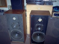
Digging up a long dead thread!
I read all through this (& the 66 thread) a while back when it was theoretical and again now as I've gone mad & bought a pair of black front 44's which it has to be said when I got them home weren't quite the buy I'd hoped..
So I've been making notes, changing them, then changing them back on the ebb & flow of advice & experience till I'm thoroughly confused..
My 44's have tatty cabinets & grilles (fixable) one dead & one dying tweeter and the caps are obviously well past their best (hard wired crossovers, black Elcaps, 6uf in parallel with the midrange orange 24uf)
So my plan of action is to refinish the cabinets & do some work on the grilles to minimise their effect (they are necessary in my case & I feel done properly they can offset the effects of the raised surround)
I'll change the tweeters to Seas 19TFF with 10ohm in parallel & 1ohm5 in series with the tweeter cap 'bundles' replaced with Solen 400v 4&6uf
Mids I'd change to 30uf Solen with 2ohm2 and 6uf with 2ohm7.
Bass replace the 72uf's with standard 72uf 50v Alcap electrolytics (as being the closest to original)
I know I can get much better polyprops but frankly I'm not prepared to spend the cash, would I be better just replacing like for like with Alcaps & forgetting polypropylene all the inelegant ESR resistors?
To be honest I'd not bother at all & just stick with my B&W DM2's & listen to the music - except even in the state they are & plonked directly on the floor with no thought they have *magic* & so much potential I don't think I *can* go back!
If anyone is still reading this thread I'd appreciate thoughts of comments
All the best
My advice, obvious really, is only to do as much work as is necessary to decide whether you want to keep them, otherwise you could waste a lot of time and money.
So that means replacing the tweeters and the caps. I would go with what you suggested - there's no point in wasting money on fancy caps because in my opinion they're unlikely to make a discernible difference to the sound unless they're of a different value, in which case they could do more harm than good.
It's not necessary to make cosmetic changes at this stage but if you want to, replacing the speaker cloth is very easy - just take off the old cloth, wrap some new cloth around the boards and staple it to the back, trimming off neatly after you've stapled. The cabinets you can just lightly sand down and re-finish as you wish - I did a pair in matt black woodstain once and they came up beautifully. But a word of warning - the veneer is incredibly thin and it's so easy to go through it - don't use an electric sander or you'll go through for sure.
You'll find the 44s are far warmer and far less analytical than the DM2s - a very analogue sound! - with more bass, of course. If you really want to bring out the bass, put the cabinets in the corner of a room - it will make a vast difference but is frowned upon in audio circles.
Hey rwtomkins!
Thanks for the advice & pulling me up short, I am kind of famous for going off half cocked (!) I might just start with a straight restoration job (like Kat Manton) the tweeters & matching resistors obviously & just replace what actually *needs* replacing for the caps then see..
Interesting what you say about the difference in sound between the DM2 & 44's as to my ears it's been almost the opposite. My first reaction was 'my god they've got no bass' but I realised what they have is fast clean bass with definition and no over emphasis. (In my room) In fact I'd put a lot of my overblown bass down to room modes, but they seem to have disappeared with the 44's. The difference is a drum sound thump to someone hitting a taught skin with a stick.. Actually pretty much the same thing with the mids which I put down to a small light paper coned mid unit as compared to a heavy 8"Bextrene cone. Probably coloured, but fast - The treble currently of course I couldn't possibly comment on!
Will post as I do stuff..
#ZombieThread
All the best
Graham
- Status
- This old topic is closed. If you want to reopen this topic, contact a moderator using the "Report Post" button.
- Home
- Loudspeakers
- Multi-Way
- Crossover nightmare!!!!!!!