This is about 10% variation, I the results are from my measurement technique - had held infra-red temperature sensor, 1mv DMM range.
Ken
Hi Ken,
Are you pointing the infra-red temp sensor to the heatsink? Is the heatsink black or silver? I learned that if the object is reflective, the reading is not accurate.
Panson
Hi Panson,
As you know I am having some difficulties sourcing the Thermaltrak parts. Therefore I want to use alternative parts until I can get my hands on those Thermaltrak parts.
In your email you suggested MJL21193/4 as alternative devices. Can you please give us some more info on that. I think many of us are currently having a hard time sourcing the Thermaltrak devices.
Hi Panson,
As you know I am having some difficulties sourcing the Thermaltrak parts. Therefore I want to use alternative parts until I can get my hands on those Thermaltrak parts.
In your email you suggested MJL21193/4 as alternative devices. Can you please give us some more info on that. I think many of us are currently having a hard time sourcing the Thermaltrak devices.
Sure! I will post some info here tomorrow. My domestic helper fired us last night. It is a chaos for us, a family having two little kids.
Hi Ken,
Are you pointing the infra-red temp sensor to the heatsink? Is the heatsink black or silver? I learned that if the object is reflective, the reading is not accurate.
Panson
Hi Panson,
Nice build!
I'm pointing it at the transistor, I put a piece of black paper covering the heat sink to avoid the reflections off the heat sink. I move the sensor slowly across the surface of the transistor until I see the highest temperature. I hold the sensor about 6 inches away from the transistor, at this distance the laser pointer and the sensor are not aligned.
Ken
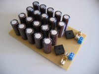
After two weeks of travelling from Hong Kong to the Netherlands the PCB's arrived! They look great! Next job is picking components which can be fit on the board and making some last efforts in order to get those NJL0302's. Anyone who can help me!? (in Europe, due to shipping time)
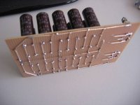
It has been a while but we have a tiny update;
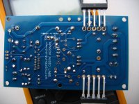
I just soldered it but it is too late to test/measure it so I want to show you my "skills". Please Panson, can you check my board before I put +/- 45 V on it?
I just soldered it but it is too late to test/measure it so I want to show you my "skills". Please Panson, can you check my board before I put +/- 45 V on it?
Attachments
I just soldered it but it is too late to test/measure it so I want to show you my "skills". Please Panson, can you check my board before I put +/- 45 V on it?
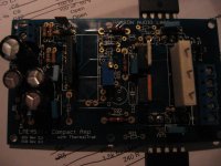
The lighting of the last photo (Compact amp) was not right. I can't see thing clearly. Please take another photo with proper lighting. Thanks!
Attachments
Attachments
Last edited:
Btw, every modern internet connection can load 5 MB in 10 seconds right?
No.
Hi SuperR,
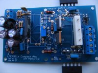
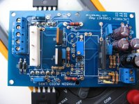
You have all e-caps and diodes in correct position. You should add heatsink to LME49811, Q1 and Q2. I think you have change some resistors' value slightly. Gain setting R7 and R8 should meet the min gain specified in the data sheet. You seem to use 330R for R7. The gain is a bit lower than 26 dB which is specified as the min. in the data sheet.
Please don't forget to set the trim pot to min resistance. Use two 10 ~ 33R 2W resistors at the rails to limit current in case of problem. Short the input to ground as well. Also make sure you supply is operating properly.
Measure the voltage drop across the above current limit resistor. You should not see any voltage higher than 1 V. Then check output DC offset level. It should be less than 10 mV.
Panson
Answering Panson;
-they are 220 and 5k6 (at least, should be") )
)
-is that turning it clockwise? or counter-clockwise? Turning it clockwise makes the resistance between r12 and r22 the least. (+/- 2 ohm at the moment)
-you mean 2w resistors between the psu and the compact amp pcb?
-k, I'll do that.
Thanks for looking at my project. Since you used different caps I wasn't sure about them so that's why I put the pictures on the internet. The silver mica looks different and the 460pf too.
ps. your "Sea of Caps" looks quite like mine
I think you have change some resistors' value slightly. Gain setting R7 and R8 should meet the min gain specified in the data sheet. You seem to use 330R for R7. The gain is a bit lower than 26 dB which is specified as the min. in the data sheet.
-they are 220 and 5k6 (at least, should be
)Please don't forget to set the trim pot to min resistance.
-is that turning it clockwise? or counter-clockwise? Turning it clockwise makes the resistance between r12 and r22 the least. (+/- 2 ohm at the moment)
Use two 10 ~ 33R 2W resistors at the rails to limit current in case of problem. Short the input to ground as well. Also make sure you supply is operating properly.
-you mean 2w resistors between the psu and the compact amp pcb?
Measure the voltage drop across the above current limit resistor. You should not see any voltage higher than 1 V. Then check output DC offset level. It should be less than 10 mV.
-k, I'll do that.
Thanks for looking at my project. Since you used different caps I wasn't sure about them so that's why I put the pictures on the internet. The silver mica looks different and the 460pf too.
ps. your "Sea of Caps" looks quite like mine
Last edited:
 Images resized and compressed.
In future, please resize your photos to no larger than 1000 pixels on the long dimension. 800 is generally just fine. Save Jpg files with medium quality compression. Target a file size not bigger than 80K.
This will help forum members on dial-up, 3G and those who have other bandwidth limits. Thanks!
Please check the resistance between R12 and R22. Make it zero ohm.-is that turning it clockwise? or counter-clockwise? Turning it clockwise makes the resistance between r12 and r22 the least. (+/- 2 ohm at the moment)
Yes.-you mean 2w resistors between the psu and the compact amp pcb?
ps. your "Sea of Caps" looks quite like mine
Yeap.
Ahh bad news, something isn't going as planned. I did what you told me;
Put some sort of heatsink on the chip+transistors (isolated)
Short circuit the input
Put resistors in the power lines (3 x 39 ohm)
Measure the voltage over the resistors
Measure the voltage on the loudspeaker output
I measure a DC value of several hundreds of millivolt at the output
I measure 0.6 V on the V+ line resistor and the GND resistor and 0.0 V on the V- line.
Where to start looking for problems? I will take the board to a place where they have a nice regulated symmetrical power supply. But of course I want to know what might be wrong.
Last edited:
We have lift-off! Connecting the jumper in order to make the chip go out of shutdown really helped a lot. The question remains however why I have dc offset when it is not driving the transistors. It hasn't produced any sound, but so far, so good.
For all you measurement tools fanboys out there I have some pictures.
ps. When all desks are filled with pc's, boxes with tools/components and datasheets, you need to find a different place to put your stuff.
For all you measurement tools fanboys out there I have some pictures.
An externally hosted image should be here but it was not working when we last tested it.
An externally hosted image should be here but it was not working when we last tested it.
An externally hosted image should be here but it was not working when we last tested it.
ps. When all desks are filled with pc's, boxes with tools/components and datasheets, you need to find a different place to put your stuff.
Last edited:
Do you see such DC offset if an, say, 8 R dummy load is connected?An externally hosted image should be here but it was not working when we last tested it.
Is it the output square wave of the amp?
- Home
- Amplifiers
- Chip Amps
- Compact Sized LME49810/11 +ThermalTrak Amp