If somebody wants to take on the combined forces of Mr. Self, and the engineering staff of Texas International, then I, for one, am eager to witness the match. Taking all bets.
The problem is not us. It is your interpretation. You clearly do not understand the topic, so you believe TI, Self, myself, Bonsai, AndrewT, are disagreeing. We are not. We are all talking the same language, we all know the topic pretty well.
Or, as before, if I've misunderstood or misinterpreted something, then I'd like very much to hear about it.
So far, your postings are exactly the opposite of "like to hear about it".
Necessarily in the context of the posted circuit, since if you don't refer to that then how do you expect your comments to be understood?
I have. You didn't. Plain enough?
Edit: you should have copied the next sentence in the TI note as well.. and I quote:
Otherwise, large currents flowing along a ground conductor will generate voltages on the conductor
Note they only refer to the IR drop. Star grounding of low inpedance circuits also introduces mutual coupling (magnetic coupling between two parallel wires). In 3 dimension space, it is possible to have three wires approach a star ground without mutual coupling. But only if each wire is 90 degrees with respect to the other two, as in a 3 axis orthogonal coordinate system (this does not work when the star node is near a conductive surface of course, the eddies of the surface modify the field lines, killing orthogonality. Beyond 3, you have to eliminate either the aggressor wire broadcast (as I describe using triax), the victim wire reception (placing the victim wire inside a tubular conductor removes the mutual coupling from the tube to the victim), or put something physically in between to modify the flux line paths. This can be done either with high permeability materials, or conductive ones which produce Lenz exclusion effects caused by eddy currents.
BTW, the assumption that only IR drop is the coupling mechanism is consistent with the pro audio industry. They've historically ignored mutual coupling, which is incorrect.
jn
Last edited:
.
And now you dragoon into service poor Bob Cordell, who willy-nilly must join the affray. Well if that is your will, then sobeit.
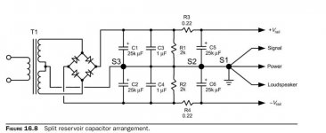
The posted illustration is from Mr. Cordell's "Designing Audio Power Amplifiers." Obviously it's figure 16-8, discussed in section 16.9, "Grounding Architectures."
.
And now you dragoon into service poor Bob Cordell, who willy-nilly must join the affray. Well if that is your will, then sobeit.
The posted illustration is from Mr. Cordell's "Designing Audio Power Amplifiers." Obviously it's figure 16-8, discussed in section 16.9, "Grounding Architectures."
.
Attachments
.
And now you dragoon into service poor Bob Cordell, who willy-nilly must join the affray. Well if that is your will, then sobeit.
The posted illustration is from Mr. Cordell's "Designing Audio Power Amplifiers." Obviously it's figure 16-8, discussed in section 16.9, "Grounding Architectures."
.
Don't be silly. That is a schematic, not a built device. It doesn't detail the mutual couplings, the loops to avoid by layout or design. He only prevents IR drop I/O coupling. He assumes YOU understand layout techniques. He can't draw in and caution against every screwup people like you can possibly make.
That is what we are trying to teach you. Perhaps you are spending too much time playing video games, and not enough learning E/M?
jn
The DC resistance is tiny. At frequency, it is no longer tiny.
You can't presume that. Resistances in general don't vary significantly with frequency, certainly not in the range we're talking about, but the capacitive reactance drops.
I don't disagree with you in absolute principle, I just disagree with you regarding significance, and I think you dismiss the difficulty of achieving symmetrical cancellation with 3 wires because it's inconvenient to your argument.
Take a look at Doug Self's recommendations regarding the the decoupling of opamp power supplies. Many people here insist that both +ve and -ve pins should be decoupled to ground. Doug says no, 1 cap, rail-to-rail. Now if that works, it works because both rails are at AC ground.
Go to the diagram in post 119, and explain why that will not oscillate at high frequency. That is how badly the inter-chassis or board layout is.
I am not in the business of defending bentsnake's assertions.
You can't presume that. Resistances in general don't vary significantly with frequency, certainly not in the range we're talking about, but the capacitive reactance drops.
I was speaking of inductive reactance.
I don't disagree with you in absolute principle, I just disagree with you regarding significance,
There's been no hard discussion of significance here. Should the OP actually build and test something, perhap there would be.
Power IC's with high bandwidth will most certainly be susceptible to it, bog standard slow stuff, less so.
and I think you dismiss the difficulty of achieving symmetrical cancellation with 3 wires because it's inconvenient to your argument.
Who said I dismiss the difficulty? I even posted and described a wire I made which completely cancels external magfield. Anybody can take a piece of triax and easily achieve symmetrical cancellation.
Twisted triad configuration almost cancels symmetrically, the only non ideal aspect is the helix path of each pair around the third. At 5 to 10 twist pitches, the external field has integrated out.
Stripline is actually one of the easiest, but only if you use flat braid as the conductors. Braid allows flexure without buckling, where copper foil does not do that well. If sandwiched properly, it's possible to make external fields almost non existent 5 thicknesses away from the line.
Triax is still the easiest and best.
Take a look at Doug Self's recommendations regarding the the decoupling of opamp power supplies. Many people here insist that both +ve and -ve pins should be decoupled to ground. Doug says no, 1 cap, rail-to-rail. Now if that works, it works because both rails are at AC ground.
No, wrong conclusion. Perhaps you should examine the structure of the chip itself and the parasitics involved around the chip.
I am not in the business of defending bentsnake's assertions.
Fair enough.
jn
Take a look at Doug Self's recommendations regarding the the decoupling of opamp power supplies. Many people here insist that both +ve and -ve pins should be decoupled to ground. Doug says no, 1 cap, rail-to-rail. Now if that works, it works because both rails are at AC ground.
I have used one 100nF ceramic between the 2 power pins with success but when I added 2 higher value electrolytics in the mix where the power comes into the circuit PCB tying each from rail to ground and twisting the 3 wires together from circuit PCB to PSU, it lowers the noise floor of my projects. Which makes it worth the hassle IMO because I hate noise.
I clamp one end of the 3 wires and tighten the other end in the chuck of a drill. Not as scientific as braiding but it gets them tight fast.

...triax ... easily...
My point being that taking 3 individual conductors and twisting or braiding them may give little better result than 2.
My point being that taking 3 individual conductors and twisting or braiding them may give little better result than 2.
Ah, your point was not clear to me.
The two rails and the load return are twisted as three simply because the wiring does not know which rail the return current came from. Twisting only the positive rail to the ground will reduce positive load current field, only negative twisted to ground reduces negative swing current field. With all three twisted, all load return current is in intimate contact with the supply current regardless of polarity.
Twisting only two does not control both polarity fields.
Twisting only the rail wires as B did in #119 will only help rail to rail conduction currents, and all output load current will return to the supply via a wire that is not near the rail wires.
jn
Ah, your point was not clear to me.
The two rails and the load return are twisted as three simply because the wiring does not know which rail the return current came from. Twisting only the positive rail to the ground will reduce positive load current field, only negative twisted to ground reduces negative swing current field. With all three twisted, all load return current is in intimate contact with the supply current regardless of polarity.
Twisting only two does not control both polarity fields.
jn
No. What we're interested in is minimizing the return loop area. If the AC voltage on the +ve rail is coupled onto the -ve rail, it will return to the PSU, if the -ve rail presents the most favourable path.. This is because each rail is effectively AC ground for the other rail. This is why it is important to twist the rails together, but not so important to include the ground.
...all output load current will return to the supply via a wire that is not near the rail wires.
This is normally the case. The speaker wire cannot be anything but remote from the rails. The load return is normally unceremoniously connected to a spur at the midpoint between the +ve and -ve PSU caps.
No. What we're interested in is minimizing the return loop area. If the AC voltage on the +ve rail is coupled onto the -ve rail, it will return to the PSU, if the -ve rail presents the most favourable path.. This is because each rail is effectively AC ground for the other rail. This is why it is important to twist the rails together, but not so important to include the ground.
This is normally the case. The speaker wire cannot be anything but remote from the rails. The load return is normally unceremoniously connected to a spur at the midpoint between the +ve and -ve PSU caps.
Go back to my simple drawing, it explains it all. post # 144
You speak of voltage.. I speak of current. Load current
jn
Yes, voltage. I presumed magnetic coupling, so EMF = rate of change of magnetic flux with time. Current depending on impedance. Of course there may be capacitive...
Anyway voltage is what you're interested in when it couples into the input (and output) of your amplifier.
I never mentioned voltage in the context of the load return. I don't know why you bother with these debating tricks, I wouldn't lower myself to that kind of thing, I prefer an honest insult. This is supposed to be a scientific examination, not a rousing speech to a lynch mob.
So is it not the case that the load current return in many installations is normally unceremoniously connected to a spur at the midpoint between the +ve and -ve PSU caps, largely without regard to the proximity of the supply rails?
There is no positive to negative rail current.
Doesn't the quiescent current flow use these?
Friends:
Looking at the document posted at HIFISONIX.com, titled, "How to Wire up an Audio Power Amplifier for Zero Noise Problems," I wanted to verify that the chassis isolation network, consisting of a bridge and 15 ohm resistor is correctly shown. In the figure, it seems that the + and minus terminals of the bridge are wired together with no other connections; one AC terminal goes to the chassis and AC inlet; the other AC terminal goes to the "T" ground.
This seems to be at odds with the ESP schematic, which has been posted (often without attribution, but then again I'm not sure who came first) on this DIYAudio site. The ESP schematic shows the AC terminals of the bridge tied together; and the plus and minus terminals tied together, with the resistor (and a capacitor) connected between the tied-together AC terminals and the tied-together plus/minus terminals.
Can anyone verify the proper schematic, or if both are alternate acceptable approaches?
Geary, you may be looking at an older version of the document. Here is the updated version
http://hifisonix.com/wordpress/wp-c.../How-to-wire-up-a-Power-Amplifier_Updated.pdf
One end of the AC terminal is attached to the chassis and the incoming GND from the inlet is attached to this point as well - so the chassis is solidly connected to the mains ground. The other rectifier AC terminal is attached to the amplifer 0V rail. The + and - are indeed shorted together but not connected to anything else. If AC mains is accidently applied to the amplifer circuit, the rectifier will clamp the fault voltage to 2 x Vbe.
You can also do it the way Rod Elliot does it, in which case the clamp voltage is 1 Vbe.
Both approaches work equally well.
For RFI, a small capacitor can be placed across the AC terminals - typically 1nF to 10nF will do the trick.
Last edited:
The "problem" is that Bentsnake is repeatedly showing erroneous schematics in Threads all over this Forum and recommending his "flawed" methods to anyone and everyone that has less knowledge than himself.Don't expect people who design for a living to do it for you for free, especially when you treat them like you have in this post.
Sounds like you are pretty sure of yourself so build it and let us know how it turns out.
Bentsnake has been doing this for weeks and refuses to listen to any advice.
We can't stop him posting.
What can we do to undo the "harm" he has already done?
This seems to be the view of D.Self........... This is why it is important to twist the rails together, but not so important to include the ground..................
I think he and you are wrong on this aspect.
All three supply wires (+ve, 0, -ve) must make a triplet.
Similarly the three wires from a centre tapped transformer must also make a triplet.
That is a non changing current.Doesn't the quiescent current flow use these?
We are discussing the effects of changing currents.
A non changing current is DC (Direct Current). DC gets no benefit from local decoupling.
It's the changing currents that get the benefit from local decoupling.
It's the changing currents that create the interference fields.
Last edited:
- Status
- Not open for further replies.
- Home
- Source & Line
- Analog Line Level
- Comment on Grounding Scheme?