Patrick Bateman said:Recently I built a bandpass sub, and much to my surprise, it seemed louder than my tapped horn. Even though the tapped horn was bigger, and used the same driver.
This was quite a shock, so I researched things, and I think I've solved the mystery.
The problem is that almost everyone is modeling their tapped horns in eigth space, and that's just ridiculously optimistic. In addition, the excursion simulations from horn response seem a bit suspect I'm afraid
While the jury is out on which program accurately models excursion, I am confident that anyone who compares a tapped horn modeled in eighth space to a vented box simulation from any other program, is going to get bogus results.
Here's how I came to this conclusion:
http://www.diyaudio.com/forums/showthread.php?postid=1597059#post1597059
Just makes me wonder as to what happens to the horn action if it works the same (or worse in your case) as a reflex port?
NoMikeHunt79 said:
Thanks very much.I put Le in as 0.5mH just for testing, you don't know this value also do you?
Sadly, it can´t be calculated o or derived from the given data. Since the Speaker isn´t one of the heavier-coned longthrow/high excursion types, a Le of around 0,6 - 1,2 seems a feasible starting point. It´s cone is very light, I doubt it will handle strong compression ratios over 3:1 in a prosound-Environment, the cone probably isn´t rugged enough. The mechanical losses seem to be quite low for a speaker this size, a clean and punchy sound should be possible.
This is not a real subwoofer, more than a Bass/Midbass Driver, intended for Prosound-Tops. I found these types of drivers to work quite well in tapped-horns, so I´m looking forward to your results
Patrick Bateman said:In addition, the excursion simulations from horn response seem a bit suspect I'm afraid
Hi Patrick Bateman,
How did you measure your excursion?
Bjørn Kolbrek has recently reported that Hornresp's diaphragm displacement predictions are in fact quite close to measured results.
http://www.diyaudio.com/forums/showthread.php?postid=1591527#post1591527
Kind regards,
David
Hello David, Patricks problem is that he had assumed 0,5PI in his simulations, like he says in his other TH thread (see quote), while he had no perfect 0,5PI situation in his home. That the simulation differs from reality in such a situation, is inevitable.
Patrick Bateman said:I hate to say it, but there's a big fat fundamental flaw to all the tapped horn simulations that everyone's been doing here.
Well here's the prob. Everyone is doing their simulations as if the tapped horn is perfectly corner loaded.
MaVo said:Hello David, Patricks problem is that he had assumed 0,5PI in his simulations, like he says in his other TH thread (see quote), while he had no perfect 0,5PI situation in his home. That the simulation differs from reality in such a situation, is inevitable.
There are a ton of people on this thread doing simulations in 1/2pi and 1pi, and wetting their pants when they see SPL graphs that predict efficiencies in the triple digits.
But this is fantasy. To do a proper comparison of a tapped horn to a vented or bandpass box simulation from any other program, you need to simulate it in 4pi.
To do otherwise is to compare apples and oranges.
David McBean said:
Hi Patrick Bateman,
How did you measure your excursion?
Bjørn Kolbrek has recently reported that Hornresp's diaphragm displacement predictions are in fact quite close to measured results.
http://www.diyaudio.com/forums/showthread.php?postid=1591527#post1591527
Kind regards,
David
That's a relief, I knew that one program or the other was giving suspect displacement results, since they're off by a factor of 50%. I really like your program, the wizard in particular is pure genius.
For my other simulations I'm using bandpass boxmodel, which I've found to be more thorough and accurate than anything else that's free. One thing about it that I like is that it will calculate all other parameters for you, which is excellent when you have partial measurements.
http://www.hal-pc.org/~bwhitejr/
Don Snyder said:Over on the Hornresp thread, I asked David McBean "Does Hornresp expect the hole in the baffle of a tapped horn to be equal to the area at S2? "
He replied "No, not at all. The Hornresp tapped horn simulation model is quite flexible in this regard. Note that as from Version 18.10 a throat chamber can now also be included in the design, if required."
This is a really handy new feature. I messed around with some tapped horn simulations and was able to dramatically alter the response by including a coupling chamber.
If you want to learn how to calculate the chamber, the math is in Marting King's horn theory pdf over at quarter-wave.com.
That's a bit of work, so a shortcut is to use a calculator designed for bandpass boxes. That's because the math required to calculate the coupling chamber volume for a front loaded horn and for a single reflex bandpass is the same. Here's my favorite one:
http://www.carstereo.com/help/Articles.cfm?id=28
If David Mc Bean reads this post, could you answer a question I have?
When you use a coupling chamber (or throat chamber) with a tapped horn, where does the rear wave tap into? Does it tap into the chamber itself, as it would in a dual reflex bandpass that's tuned in series? Here's a pic:
http://photos-b.ak.facebook.com/photos-ak-sctm/v203/137/0/829895047/n829895047_2231169_5608.jpg
Or toes the rear wave tap into the throat of the front horn?
I don't have a pic of what that would look like, but imagine the subwoofer above, except the rear port would be connected to the throat of the front port.
There are a ton of people on this thread doing simulations in 1/2pi and 1pi, and wetting their pants when they see SPL graphs that predict efficiencies in the triple digits.
But this is fantasy. To do a proper comparison of a tapped horn to a vented or bandpass box simulation from any other program, you need to simulate it in 4pi.
To do otherwise is to compare apples and oranges.
You honestly didn't think of this until now? Really? I guess it makes sense, since I've never heard anyone ask or talk about this issue before, but for at least a couple of years now I've been very skeptical about comparing sims (especially of different types of enclosure) to sims done with a different program, differences in radiating space being only one concern. For example, I would compare a tl sim done with MJK's software to a ported winisd sim, and take the results with a grain of salt.
Now that I've figured out hornresp, and hornresp is capable of modelling almost everything I'm interested in, I just model EVERYTHING in hornresp. Then you don't have to worry about anything, and you can use 2 pi or 4 pi or whatever you like, as long as you use the SAME environmental considerations for each.
just a guy said:
You honestly didn't think of this until now? Really? I guess it makes sense, since I've never heard anyone ask or talk about this issue before, but for at least a couple of years now I've been very skeptical about comparing sims (especially of different types of enclosure) to sims done with a different program, differences in radiating space being only one concern. For example, I would compare a tl sim done with MJK's software to a ported winisd sim, and take the results with a grain of salt.
Now that I've figured out hornresp, and hornresp is capable of modelling almost everything I'm interested in, I just model EVERYTHING in hornresp. Then you don't have to worry about anything, and you can use 2 pi or 4 pi or whatever you like, as long as you use the SAME environmental considerations for each.
I purchased loudspeaker simulation software from Old Colony Sound Lab when I was 18yrs old, close to twenty years ago. So I've been doing this for a while. And I did indeed believe the hype when I saw people doing sims showing efficiencies in the triple digits for tapped horns. And that's incredibly misleading for everyone here.
In fact, upon re-reading the tapped horn paper, even Danley himself doesn't claim an efficiency advantage for the tapped horn! What he claims is that it has an advantage in sheer output over a vented enclosure, mostly due to a reduction in excursion. Quoting Danley:
"While the SPL is comparable for the two units, one of the real advantages of the Tapped Horn is seen in Figure . The diaphragm excursion of the driver is greatly reduced due to the acoustical loading of the horn. With an input of 63 V (500 W) the vented box exceeds 5 mm (0.2 inches) at 90 Hz. The Tapped Horn is well below this until just above 55 Hz. The vented box reaches 9mm at 55 & 35 Hz while the Tapped Horn’s excursion peaks at just over 6 mm at 46Hz. This decrease in excursion will translate directly into lower distortion and higher output capability from the Tapped Horn."
What do you guys think? Was I the only one who was misled to believe that the tapped horn would have a significant efficiency advantage over a vented horn of comparable size?
It's hard to believe that AA and Old Colony Sound have been around for so long.
I built the early projects of 72/73 when Walt Jung presented Active Xover and 30Hz rumble filters using Old Colony PC boards.
When S/B printed the Apple Basic version of BOXRESPONSE in 84, I immediately converted it to run on an IBM PC (64k).
Crude as it was that program was a great time saver and as S/B posted changes I updated my version, and used it for many years.
It's a 1st gen. relic compared to the wide variety of sim software available today.
Patrick Bateman said:
If David Mc Bean reads this post, could you answer a question I have?
When you use a coupling chamber (or throat chamber) with a tapped horn, where does the rear wave tap into? Does it tap into the chamber itself, as it would in a dual reflex bandpass that's tuned in series? Here's a pic:
http://photos-b.ak.facebook.com/photos-ak-sctm/v203/137/0/829895047/n829895047_2231169_5608.jpg
Or toes the rear wave tap into the throat of the front horn?
I don't have a pic of what that would look like, but imagine the subwoofer above, except the rear port would be connected to the throat of the front port.
I believe I answered my own question. In a tapped horn, it looks like the coupling chamber would fire into the narrow end of the tapped horn. I had it backwards, thinking that the coupling chamber would contribute it's output in the 2nd throat, not the first.
Patrick Bateman said:
There are a ton of people on this thread doing simulations in 1/2pi and 1pi, and wetting their pants when they see SPL graphs that predict efficiencies in the triple digits.
But this is fantasy. To do a proper comparison of a tapped horn to a vented or bandpass box simulation from any other program, you need to simulate it in 4pi.
To do otherwise is to compare apples and oranges.
I think 2 pi is the appropriate way to model these unless your flying them in the air.
Its probably difficult to get these out of Half space (2pi) are you going to drag your tapped horn into free space (4pi) on a tower somewhere?
1/4 (1pi) and 1/8th (.5pi) space are a little tough unless you've got concrete or rock surfaces.
This would be a useful way of modeling 2 or 4 of the cabs at once if they are all close coupled.
Antone-
sumsound said:I think 2 pi is the appropriate way to model these unless your flying them in the air.
Its probably difficult to get these out of Half space (2pi) are you going to drag your tapped horn into free space (4pi) on a tower somewhere?
Antone-
Jim Bell's got them on the stadium pressbox, but that doesn't
qualify for 4Pi, 'cause he's got an array of 4.
See the thread <jbell's set of four tapped horns> for some great pics.
Patrick Bateman said:I believe I answered my own question. In a tapped horn, it looks like the coupling chamber would fire into the narrow end of the tapped horn. I had it backwards, thinking that the coupling chamber would contribute it's output in the 2nd throat, not the first.
Hi PB,
Just to confirm - for a tapped horn, Hornresp assumes that the throat chamber is located between the throat-facing side of the driver diaphragm, and the S2 entry point. This can be readily seen in the schematic diagram, when Atc <> Sd.
The location of the throat chamber is consistent across all horn loudspeaker configurations considered by Hornresp.
Kind regards,
David
Tom Danley made some comments on my Tapped Horn for Dummies thread that are quite interesting:
http://www.diyaudio.com/forums/showthread.php?postid=1598351#post1598351
http://www.diyaudio.com/forums/showthread.php?postid=1598351#post1598351
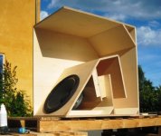
Here's my version of Jim's Tapped Horn. I ran this by Jim, and he suggested that I share it with the forum. This thing is BIG, over 600 liters, but that's not a problem for a fixed install.
The average guy should be able to get all of the saw-work done at a decent lumber yard, and complete it in an afternoon. If all the 24" cuts are actually 23 3/4", and cut with one set-up, he can even use PVA and everything will fit perfectly. If he's got a router and a laminate trimmer bit, he can even make it pretty.
The angle cuts on the front and the baffle are a little over 8 degrees, but Jim said he left them square and used PL Polyurethane expanding adhesive. No bracing is shown, which is either brave ... or foolish. Jim put triangles in the two back corners (see pic in <jbell's set of four tapped horns> thread).
Oh, and the driver is centered on the baffle.
~Don
Attachments
I finished the second and final tapped horn today. This one will be used by my younger brother in his dorm room XO'd at 60hz to his dayton refrence MTM's. I wont be able to hook them both up at the same time until this summer. One did sound cleaner and more authoritative than 2 sealed and 1 ported sub playing at the same time though. I can only assume that 2 of these tapped horns will be even more impressive.
Eventually I will have these XO'd to an OB midbass array of 8 10's per side (l @ r)at 60hz that will go up to 150-200hz.
Eventually I will have these XO'd to an OB midbass array of 8 10's per side (l @ r)at 60hz that will go up to 150-200hz.
The 'Hog' looks to be half scoop, and half tapped horn.
Here is another from the same site. No real design, he just butchered some wood together. I analyzed it and suggested he add the board shown in black.
Here is a 'Hog' type that I analyzed:
The really large mouth seems to give the big low end bump, the large back volume seems to give the big dip 100hz~150hz.
- Home
- Loudspeakers
- Subwoofers
- Collaborative Tapped horn project