Close coupled horns is an apples n' oranges comparison because there's more drivers, power handling capability to offset the lack of a 'perfect' corner.
You're right though about a below grade corner in a poured concrete basement if the floor above is rigid/massive enough or even the better constructed homes the colder climes require. The only really ~optimized audio/video room I did was in such a basement and taming the excessive LF to use the existing corner loaded high LF gain speakers required considerable effort, but well worth the results.
But mine and many others rooms I've crudely measured along with others who've posted results on HT forums get a response similar to djk's, so reinforcing corners with at least 1.5" thick no void plywood is a good plan. In my previous home which already had a brick facade and well insulated walls on a poured concrete pad, I bricked the inside with a nice white brick to get near the theoretical gain curve down to below 20 Hz where the ceiling became ~ acoustically transparent, but back then I had no source other than an audio generator that went this low, so there was no need to deal with it.
GM
Re: PYM1298
'Default' ~21 Hz conic/~392.6 L net, 1 W, half space (shaded response = ~14 Hz conic/~873.3 L net):
GM
zlast said:Anyone used or modeled this driver in a tapped horn?
'Default' ~21 Hz conic/~392.6 L net, 1 W, half space (shaded response = ~14 Hz conic/~873.3 L net):
GM
Attachments
Re Post #2318
Hi Djk,
I've seen this graphic sometimes.
If I remember correctly the measuring of the EAWs BH FLHs was done in open field on ground, where some trees appear in the photos.
Should the ground explain the absence of half space gain which appears in theory as well as in simulation programs?
Can the ground in this situation function as absorvative no reflective material?
Regards, Paulo.
how well would one or two (clamshell) work in a 50hz - 150ish hz tapped horn?
PARAMETERS
Re 7.20 [ê ]
Fs 44.26 [Hz]
F1 35.48 [Hz]
F2 56.23 [Hz]
Zm 53.74 [ê]
D 208.00 [mm]
Qms 5.80
Qes 0.90
Qts 0.78
Bl 6.76 [N/A]
L1K 1.47 [mH]
L10K 0.72 [mH]
Ms 20.47 [g]
Vas 101.85 [l]
dBSpl 92.34 [dB]
Cms 0.63 [mm/N]
Ma 48.00 [g]
FsMa 24.20 [Hz]
PARAMETERS
Re 7.20 [ê ]
Fs 44.26 [Hz]
F1 35.48 [Hz]
F2 56.23 [Hz]
Zm 53.74 [ê]
D 208.00 [mm]
Qms 5.80
Qes 0.90
Qts 0.78
Bl 6.76 [N/A]
L1K 1.47 [mH]
L10K 0.72 [mH]
Ms 20.47 [g]
Vas 101.85 [l]
dBSpl 92.34 [dB]
Cms 0.63 [mm/N]
Ma 48.00 [g]
FsMa 24.20 [Hz]
"Should the ground explain the absence of half space gain which appears in theory as well as in simulation programs?"
No, and that was the point of posting the graph.
At 200hz the stack is 115dB/W/1M, and shows 5dB of gain over a single cabinet with 1W.
I've owned Klipschorns, and sold them (as a dealer).
They have very good bass (40hz) in a below grade room, no real deep bass in a old house with heavy plaster-and-lath construction, and no bass in a room on a concrete slab that had sheet-rock over metal studs on 2' centers.
As regarding sims, it doesn't really matter that they can't accurately model in 1Pi, 0.5Pi, or cabinet construction. The room is what it is, and all your designs will probably have similar construction build. From that standpoint the sims do give us a reference for comparison.
Chris8sirhC said:how well would one or two (clamshell) work in a 50hz - 150ish hz tapped horn?
Not too well since the HF mass corner is 2*44.26/0.9 = 98.36 Hz and due to its highish Qts it wants a tuning down around 44.26*0.9/2 = 19.92 Hz for a ~30 Hz low end, though you could scrunch it up to 50 Hz, but considering how big it will be it doesn't seem worth it for only an octave (~645 L clamshelled).
BTW, which make/model driver is this? Any idea what the Xmax is?
GM
its this one:
http://www.diyaudio.com/forums/showthread.php?postid=1594887#post1594887
http://www.partsexpress.com/pe/pshowdetl.cfm?&DID=7&Partnumber=299-721
x-max is only 3mm. They can take only 30 watts. Ive had these stupid things for years now, and I cant really seem to come up with anything that really works for them.
Hmm, two clamshelled gets you an effective 6 mm Xmax and 1.5 ft^3 sealed gets you a 50 Hz F3, so if ~110 dB peaks is enough........ otherwise two clamshelled pairs in 3 ft^3 sealed is another 6 dB and add another channel for 3 dB more, etc., so there's your ~50-150 Hz BW in a relatively compact system with comparable SPL performance of the TH, though of course much more power is required to offset the lack of the TH's huge cab, ergo potentially audible thermal power compression. Not many 'free lunches' in audio.
GM
GM
Building a TH with a long L34?
I'm trying to realize a build plan from my HR data and I'm having trouble with a long L34 (80 cm).
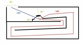
Any reason this layout won't work? It's the only way I can see to achieve a long L34 with out making the horn too deep.
The diagram isn't to scale, it's just a rough sketch to illustrate mounting the driver about 1/2 way along the last section of tapper. Most of the designs I see here have the driver in mouth. Having S4 only slightly larger than S3 does not seem to have much effect on the FR.
I'm trying to realize a build plan from my HR data and I'm having trouble with a long L34 (80 cm).
Any reason this layout won't work? It's the only way I can see to achieve a long L34 with out making the horn too deep.
The diagram isn't to scale, it's just a rough sketch to illustrate mounting the driver about 1/2 way along the last section of tapper. Most of the designs I see here have the driver in mouth. Having S4 only slightly larger than S3 does not seem to have much effect on the FR.
Attachments
Re measured response appearing in post 2318
Sorry insisting but as I’m still intrigued with the graphic of post nr 2318, which are against all I’ve learned up to date about the gain we should obtain when summing horn mouths by stacking them, let’s compare the result at Wayne Parham shootout of the bellow link.
http://www.audioroundtable.com/ProSpeakers/messages/373.html
I refer to Tuba 36 (BF design) as an example who appears there with four boxes, presenting responses from 1, 2 and 4 boxes slim version.
I’ve built two of these T36 horns 28” wide (maybe for live music they can work but they lack deep bass…); wouldn’t build more…
Looking at the curves I picked the values at 40 Hz, 50 Hz, 70 Hz and 100 Hz:
So the values I find in dBs are roughly and respectively:
1 cab: 60 63 74 74.5;
2cabs: 69.5 70.5 81 82;
+9.5 +7.5 +7 +7.5
4cabs: 78 78 86.6 87;
+8.5 +7.5 +5.6 +5.5
Looking again at these numbers do they confirm or not what theory and simulation teach us?
I own some Mogales 1850 style FLHs and the response indoor when one, two and four cabs are stacked are impressive.
Regards, Paulo.
@ Steve71
That should work fine. I just completed construction of my second TH as a check of my understanding of how these work. Though I used a simpler fold, my design has a long L34 like you have in your drawing, as well as a slow expansion rate. My initial evaluation is that it seems to work as I hoped (and as Hornresp predicts).
I've not measured impedance or frequency response yet, but some purely subjective listening and A/B comparisons with my other TH indicate that the performance is similar to what I modeled. I am hearing bass notes that my other TH did not reproduce (and would not be expected to).
Anyhow - short answer - yes - it will work fine.
If you model things realistically and build what you model accurately, what you build should behave as your model predicts. If reality does not agree with your model, check your assumptions first, check your measurements second.
Re: Re measured response appearing in post 2318
I would also like to know more about the measurements")
PASC said:Sorry insisting but as I’m still intrigued with the graphic of post nr 2318, which are against all I’ve learned up to date about the gain we should obtain when summing horn mouths by stacking them, let’s compare the result at Wayne Parham shootout of the bellow link.
I would also like to know more about the measurements
Re: Building a TH with a long L34?
I designed the fold for a Lab12 driven TH for Chris. L34 simmed best at 60 cm, but 50 cm was almost as good, and allowed reaching the driver thru the mouth (no access panels).
What you have sketched should work fine!
steve71 said:I'm trying to realize a build plan from my HR data and I'm having trouble with a long L34 (80 cm).
Any reason this layout won't work? It's the only way I can see to achieve a long L34 with out making the horn too deep.
I designed the fold for a Lab12 driven TH for Chris. L34 simmed best at 60 cm, but 50 cm was almost as good, and allowed reaching the driver thru the mouth (no access panels).
What you have sketched should work fine!
Attachments
Thanks for the responses guys, much appreciated! Hopefully I'll have something built by the end of the week... and yes, I'll be building in an access panel for the driver... and to chase the cats out when they try to crawl up there .
What are you guys using to seal the sub when attaching the top? Just wood glue or liquid nails?
.What are you guys using to seal the sub when attaching the top? Just wood glue or liquid nails?
Chris8sirhC said:I used a liquid nails type product and a nail gun. Put the nails in at alternating angles to hold it in place even better. With this method I built the entire horn in about an hour. Clamp a section down then put the nails in, and move to the next section.
Chris,
Can you detail that adhesive product please? I have been using plain old yellow carpenters glue from Home Hardware brand and find that it does not stick to the hard surface finish on MDF. I have to roughen up the MDF surface where the glue joints are or else they come apart after the glue has dried if mechanically strained. This is IMO totally unacceptable.
I use a brad nailer and polyurethane-based construction adhesive (I use PL Premium because it is readily available) for my cabinets. As Chris just said - it is possible to build a cabinet this way in an evening. My recent builds have all been made of plywood. MDF may not have the moisture content necessary to cure the PL so you may need to moisten the surfaces of the joint prior to gluing.
As it cures, PL expands and fills/seals any gaps very nicely. Once cured, the beads of glue are easily cut off with a utility knife, which saves a lot of sanding.
As it cures, PL expands and fills/seals any gaps very nicely. Once cured, the beads of glue are easily cut off with a utility knife, which saves a lot of sanding.
That is the exact same glue that I use. It doesnt really expand much, but it is very thick so it fills things in nicely. I have used it on MDf before, but it has always been in conjunction with bisciuts or screws etc so I cant really comment on how strongly it will hold mdf. I have used Gorilla polyurithane glue with mdf and it seemed to work fine.
The whole glue situation is also another reason that I chose to use OSB instead of MDF on my last project. From the way it is made, it seems like it would be stronger for glue joints. Also, when using gorilla glue on mdf, i always wet the glue surfaces with a damp paper towel before i glue the speaker together bc the glue requires moisture to work. Unless you are using plywood and only gluing along multiple layers for both pieces (45 degrees) I would consider the glue as a secondary holding measure, and screws etc should be primary.
- Home
- Loudspeakers
- Subwoofers
- Collaborative Tapped horn project