Here is the 6K5 loadline example for an operating point of Va=540V and Ia=100mA. It seems like that in order to achieve Po=10W, a swing of 150V is required in the grid. Is about right?
Hi Ale,
That looks like an excellent load line for your OPT and B+ available. I would provide for 200V peak-to-peak grid drive.
mogliaa,
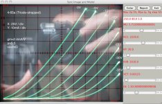
Too bad your tracer can't tell us how it really looks out in the -200 grid1 and 1600v anode region. Your model appears to get sloped curves near cut-off pretty early on. In Dave's plot it looks like the curves are perhaps a bit better behaved.
Your op point sounds good for the given B+ supply, and you're really taking advantage of more power delivered by A2 mode. I am still working on my amp which is going to allow 300vpp on the load line. 9k primary to 6ohm secondary, around 800v and 75ma bias. My speakers tend to sound better on higher damping factor tube amps, so that's what I'm going with. The A2 mode will likely only come into play on rather high volume level and transients, but it's also safe to assume that grid current can occur even before reaching 0v on the grid. This topology, you won't have blocking distortion and the slew rate is sufficient.
Make sure to have Rod Coleman provide you with some DHT supplies for the 4-65A, as this made the single largest improvement in my breadboard testing.
I'm getting closer on my amp") I've all the supplies and sub circuits completed. You'll understand why it's taking so long once I have a few pics up. I have made matching racks for the amps, which are in two boxes ea, dual mono config.
I've all the supplies and sub circuits completed. You'll understand why it's taking so long once I have a few pics up. I have made matching racks for the amps, which are in two boxes ea, dual mono config.
Too bad your tracer can't tell us how it really looks out in the -200 grid1 and 1600v anode region. Your model appears to get sloped curves near cut-off pretty early on. In Dave's plot it looks like the curves are perhaps a bit better behaved.
Your op point sounds good for the given B+ supply, and you're really taking advantage of more power delivered by A2 mode. I am still working on my amp which is going to allow 300vpp on the load line. 9k primary to 6ohm secondary, around 800v and 75ma bias. My speakers tend to sound better on higher damping factor tube amps, so that's what I'm going with. The A2 mode will likely only come into play on rather high volume level and transients, but it's also safe to assume that grid current can occur even before reaching 0v on the grid. This topology, you won't have blocking distortion and the slew rate is sufficient.
Make sure to have Rod Coleman provide you with some DHT supplies for the 4-65A, as this made the single largest improvement in my breadboard testing.
I'm getting closer on my amp
I've all the supplies and sub circuits completed. You'll understand why it's taking so long once I have a few pics up. I have made matching racks for the amps, which are in two boxes ea, dual mono config.mogliaa,
Too bad your tracer can't tell us how it really looks out in the -200 grid1 and 1600v anode region. Your model appears to get sloped curves near cut-off pretty early on. In Dave's plot it looks like the curves are perhaps a bit better behaved.
Indeed, but was tracer is complex enough as it is. I may modify the grid driver circuit in the future to allow A2 plots above +15V.
My model is a rough approximation from Dave's plot which come from Dave's model
. In the absence of this, I'm trying to work out a good approximation for initial design. Your op point sounds good for the given B+ supply, and you're really taking advantage of more power delivered by A2 mode. I am still working on my amp which is going to allow 300vpp on the load line. 9k primary to 6ohm secondary, around 800v and 75ma bias. My speakers tend to sound better on higher damping factor tube amps, so that's what I'm going with. The A2 mode will likely only come into play on rather high volume level and transients, but it's also safe to assume that grid current can occur even before reaching 0v on the grid. This topology, you won't have blocking distortion and the slew rate is sufficient.
Yes. I do have a pair of Fostex 167E, which sound really good with my 45 SE, but need some more power.
I want to breadboard the amp to play around and look how to optimise the circuit.
At the moment I'm thinking of two stages: 26 and 46, both gyrator loaded as per previous posts. I will draw initial circuit soon.
Make sure to have Rod Coleman provide you with some DHT supplies for the 4-65A, as this made the single largest improvement in my breadboard testing.
I'm getting closer on my amp
That's for sure. Rod's regulators are really good. I'm using them in my 45 and preamps.
Would be quite good to see some of your work and exchange ideas and experience.
Thanks for the help
Cheers,
Ale
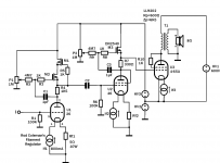
Here is my first sketch of what I'd like to get done with the 4-65a from Michael's design.
I'm happy with three stages all DHT: keen to start with 26 (or 01a) with starved filaments and filament bias and gyrator load. Then driver stage will be 46 (or 10Y) again with filament bias and gyrator as well.
For personal preferences I chose 46 as have some good sets of NOS very linear, however I have a lot of respect for the 10Y. It could be quite nice to end up with a 100% thoriated DHT amp: 01A-10Y and 4-65A
What do you guys think about this? Any suggestions?
Cheers,
Ale
Attachments
Here is my first sketch of what I'd like to get done with the 4-65a from Michael's design.
I'm happy with three stages all DHT: keen to start with 26 (or 01a) with starved filaments and filament bias and gyrator load. Then driver stage will be 46 (or 10Y) again with filament bias and gyrator as well.
For personal preferences I chose 46 as have some good sets of NOS very linear, however I have a lot of respect for the 10Y. It could be quite nice to end up with a 100% thoriated DHT amp: 01A-10Y and 4-65A
What do you guys think about this? Any suggestions?
Cheers,
Ale
I need to study this a little more. 01A and 10Y would be a nice amount of gain and my personal choice. Not to mention I have some old KenRad 01A and RCA VT-62 that I have been saving for an all-thoriated amp project.
I was just wondering what truly contemporary tube amp designs are out there and saw this. I would love to hear this amp, it is such a cool design. It is a shame there are only 2 groups "sand and glass", the fact is that it should really just be the best component for the job.
I need to study this a little more. 01A and 10Y would be a nice amount of gain and my personal choice. Not to mention I have some old KenRad 01A and RCA VT-62 that I have been saving for an all-thoriated amp project.
I like 01and am using it as my preamp stage at the moment. Not sure about 10Y, it has a larger Ra compared 46 as a driver. Also 10Y is more demanding on a filament bias :-(
Looks like 46 here can do a great job.
It may be a question of breadboarding and listen to them...
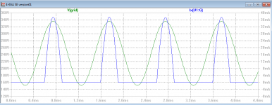
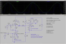
First simulation with 46 driver and filament bias. The 46 is biased at Ia=43ma and Vgk=18V approximately. Anode is at 232V and 4-65A grid is at 246V (referenced to ground). Driving the 46 with 18V (peak) signal, I can get about 9.3W and THD=0.9% when 4-65A is biased at about 104mA. Not sure if I managed to model correctly the OT, but given that this is just an approximation I hope will do the job before moving to a breadboard
The 46 mu-output signal swings 150V....
DN2540 dissipation is less than 7W so it will do fine.
Nice to see the grid current peaks
Yes, 35W on the filament power supply seems a lot, but it does pay in the sound, so given the size of this amp, I think it won't make a massive difference. The 10 ohm filament resistors will need to be 50W rate
Now need to add the 01A or 26 stage to see how it works out. ...
cheers,
Ale
Attachments
mogliaa,
Too bad your tracer can't tell us how it really looks out in the -200 grid1 and 1600v anode region. Your model appears to get sloped curves near cut-off pretty early on. In Dave's plot it looks like the curves are perhaps a bit better behaved.
Hi Michael,
Tried to plot curves on my tracer, but it has proven to be very difficult. I think the 4-65a was oscillating somehow despite 10K grid stopper and ferrite beads, or it might be the sloppy filament raw supply adding some significant ripple? Should try a hum cancelling pot next time.
Either way, attached is a second attempt to obtain a model for the 4-65a.
Cheers
Ale
Attachments
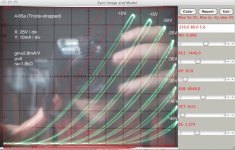
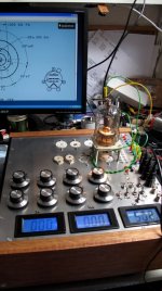
It was the sloppy DC supply. Added a hum pot and a capacitor right at the bottom of the valve. Now it looks good
0V curve is likely not to much due to grid limiting current as have grid stopper, etc.
0V curve is likely not to much due to grid limiting current as have grid stopper, etc.
Attachments
Last edited:
Been playing a bit to optimise my first version of this 4-65a SE based on Michael's design. My idea is to do 26 /46 / 4-65a. I have a 26 preamp and plan still is to maintain filament bias where possible.
The 4-65a model performs reasonably well. I did some THD measures on the 4-65a with a CCS load and if results are extrapolated is on the same lines of what should be expected.
As pe Michael's recommendations, the driver needs to provide about 200Vpp to deliver full output power given my loadline and HT constraints. As it stands I can get THD=0.88% at 14W or 0.19% at 1W.
The 4-65a is pushed close to its Pd limits: 73W (anode+screen).
I guess I can optimise the 46 to minimise distortion? I started with Rmu1=1/gm but as I increased it to 1K I reduced THD at maximum swing 0.76%. I thought that Rmu1=1/gm was the optimal value for the mu-follower. Of course I changed the Rmu without changing the bias point so this impacted the anode current, therefore I ended up with a lower Ia which set the 46 in a more linear region?
Perhaps I can tweak the 46 to find a better operating point here. It shouldn't impact that much to reduce the quiescent current as all the positive grid current is provided by the cascode?
Any suggestion of how to tweak anything else before getting into breadboard stage?
Thanks
Ale
Attachments
Been playing a bit to optimise my first version of this 4-65a SE based on Michael's design. My idea is to do 26 /46 / 4-65a. I have a 26 preamp and plan still is to maintain filament bias where possible.
The 4-65a model performs reasonably well. I did some THD measures on the 4-65a with a CCS load and if results are extrapolated is on the same lines of what should be expected.
As pe Michael's recommendations, the driver needs to provide about 200Vpp to deliver full output power given my loadline and HT constraints. As it stands I can get THD=0.88% at 14W or 0.19% at 1W.
The 4-65a is pushed close to its Pd limits: 73W (anode+screen).
I guess I can optimise the 46 to minimise distortion? I started with Rmu1=1/gm but as I increased it to 1K I reduced THD at maximum swing 0.76%. I thought that Rmu1=1/gm was the optimal value for the mu-follower. Of course I changed the Rmu without changing the bias point so this impacted the anode current, therefore I ended up with a lower Ia which set the 46 in a more linear region?
Perhaps I can tweak the 46 to find a better operating point here. It shouldn't impact that much to reduce the quiescent current as all the positive grid current is provided by the cascode?
Any suggestion of how to tweak anything else before getting into breadboard stage?
Thanks
Ale
Looks nice to me. Do you plan to make V3 and V4 adjustable, and what type of supplies? I believe the power supply types and components should be chosen very carefully, and would contribute to a majority of the performance in this amp.
-MW
V3 will be an LDN150 fet with a resistor to increase AC impedance. Typical configuration on a gyrator. Haven't included in diagram yet as still tweaking voltages there for the 46 operating point.
Other power supplies will be classic tub rectifier with CLC stages using oil caps. Adjustment of voltage will be done by the multitap secondaries. Trying to avoid any additional sand or voltage regulators in the HT supplies...
Thoughts?
Other power supplies will be classic tub rectifier with CLC stages using oil caps. Adjustment of voltage will be done by the multitap secondaries. Trying to avoid any additional sand or voltage regulators in the HT supplies...
Thoughts?
V3 will be an LDN150 fet with a resistor to increase AC impedance. Typical configuration on a gyrator. Haven't included in diagram yet as still tweaking voltages there for the 46 operating point.
Other power supplies will be classic tub rectifier with CLC stages using oil caps. Adjustment of voltage will be done by the multitap secondaries. Trying to avoid any additional sand or voltage regulators in the HT supplies...
Thoughts?
Michael K mentions somewhere that V4 should be a well regulated voltage, since it serves as the ground reference for the 4-65a. My breadboard version of this supply was a zener string. The amp I am completing now is a UF4007 (with optimized snubber) CLC into a Salas HV in this position.
-MW
Michael K mentions somewhere that V4 should be a well regulated voltage, since it serves as the ground reference for the 4-65a. My breadboard version of this supply was a zener string. The amp I am completing now is a UF4007 (with optimized snubber) CLC into a Salas HV in this position.
-MW
Hi eboz,
You are right. Haven't look at the supplies yet. Clearly V4 needs to provide driver's quiescent current, whereas V5 is the one which provide the grid current required by the positive peaks in A2.
What Salas HV are u using? I built my own HV version 1 for my 26 preamp with great results. Have some PCBs for version 2 but haven't tried them yet. I've seen very good feedback on it so far over here. I may start with a simple zener string and a mosfet passive regulator....
That's exactly the idea. The driver supply is split such that V4 puts a relatively constant load on a stable and clean supply. V5, on the other hand, supplies the peaky grid current, but since it feeds a MOSFET drain can be rough and unregulated. V5 in the prototype was a 25VA toroid, a bridge rectifier, and an electrolytic capacitor.
PS It's a good time to mention again the protection diode to prevent the V1-V4-V5-cathode point from going negative should the anode or B+ short to ground. That would put the B+ storage cap across V4 reverse polarity...
PS It's a good time to mention again the protection diode to prevent the V1-V4-V5-cathode point from going negative should the anode or B+ short to ground. That would put the B+ storage cap across V4 reverse polarity...
Last edited:
That's exactly the idea. The driver supply is split such that V4 puts a relatively constant load on a stable and clean supply. V5, on the other hand, supplies the peaky grid current, but since it feeds a MOSFET drain can be rough and unregulated. V5 in the prototype was a 25VA toroid, a bridge rectifier, and an electrolytic capacitor.
PS It's a good time to mention again the protection diode to prevent the V1-V4-V5-cathode point from going negative should the anode or B+ short to ground. That would put the B+ storage cap across V4 reverse polarity...
Thanks Michael for the tip. Can't remember reading it before! I guess a UF4007 across V4 will be sufficient for protection?
Thanks
Ale
Thanks Michael for the tip. Can't remember reading it before! I guess a UF4007 across V4 will be sufficient for protection?
Thanks
Ale
There is a protection diode in the schematic here:
http://www.diyaudio.com/forums/tubes-valves/143687-gyrator-question-9.html#post1863890
-MW
I posted this in the SSHV thread, but this really pertains to Michael K's Meteor amp, and I'm sure he knows plenty about the stacked supplies! Going to re-post here in the hopes that Michael could have a look for me.
It is definitely a short that is created somehow when the top tube supply becomes warm and is conducting. I check the CT when it's turned off and there is no path to ground.
I am wondering if there is some reason I would not be able to stack a tube rectified supply with a SSHV1. The SSHV is working as expected when it is used independently. When testing the tubed supply independently, it also operates as expected. However, when the tubed supply is stacked on top of the SSHV, I am left with what seems to be some kind of short. I have not checked the current in this condition, but the output voltage measures as 0v. The return of the tubed supply is simply connected to the positive output of the SSHV. The SSHV supply return is connected to signal and earth ground, while the tubed supply's return is only connected to the positive terminal of the SSHV. The SSHV output does not have a load on its output, and the tubed supply output is not regulated, its only load is bleeder resistors. I should also note that the raw supply for the SSHV is SS rectified by a UF4007 FWB, and (small first C)LC filter. I'm sure that I am missing something and that someone can shed some light on this. I have stacked supplies before in prototypes, but never with an SSHV and tubed supply like this.
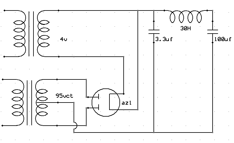
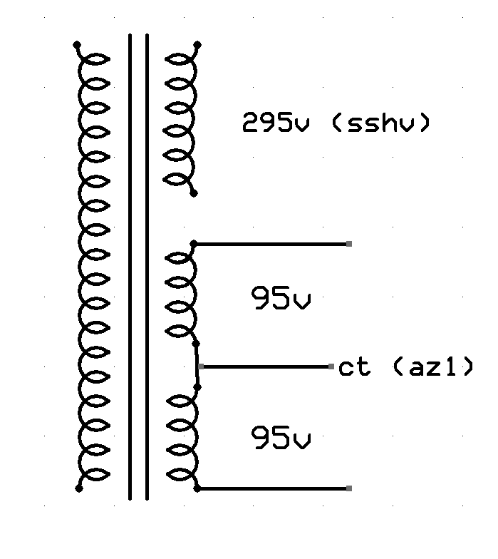
One more detail, which I hope is not the root of this problem. Both of the supplies have their windings from the same transformer. The CT of the tubed supply is actually two identical 95v windings that are connected together. I think I will double check the phase of these windings to make sure this CT is correct.
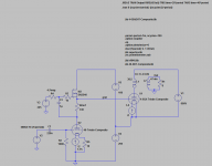
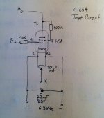
Here's how the tube supply is made:
And how the supplies are stacked:
What the PT looks like:
Regards,
-Michael Woods
It is definitely a short that is created somehow when the top tube supply becomes warm and is conducting. I check the CT when it's turned off and there is no path to ground.
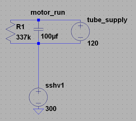
I am wondering if there is some reason I would not be able to stack a tube rectified supply with a SSHV1. The SSHV is working as expected when it is used independently. When testing the tubed supply independently, it also operates as expected. However, when the tubed supply is stacked on top of the SSHV, I am left with what seems to be some kind of short. I have not checked the current in this condition, but the output voltage measures as 0v. The return of the tubed supply is simply connected to the positive output of the SSHV. The SSHV supply return is connected to signal and earth ground, while the tubed supply's return is only connected to the positive terminal of the SSHV. The SSHV output does not have a load on its output, and the tubed supply output is not regulated, its only load is bleeder resistors. I should also note that the raw supply for the SSHV is SS rectified by a UF4007 FWB, and (small first C)LC filter. I'm sure that I am missing something and that someone can shed some light on this. I have stacked supplies before in prototypes, but never with an SSHV and tubed supply like this.
One more detail, which I hope is not the root of this problem. Both of the supplies have their windings from the same transformer. The CT of the tubed supply is actually two identical 95v windings that are connected together. I think I will double check the phase of these windings to make sure this CT is correct.
Here's how the tube supply is made:
And how the supplies are stacked:
What the PT looks like:
Regards,
-Michael Woods
- Home
- Amplifiers
- Tubes / Valves
- Class A2 Direct MOSFET Coupled SE