Hi Ale,
Thank you for your input regarding the CCS device. I will have to try this soon since it's an easy change to make. I hope that would do the trick! The crowbar seems like a good idea as well.
As a disclaimer, i've not built an amp using amorphous iron before, nor have I heard other systems using it before, so I am missing that reference point. I have done SET with transmitter output however, and I prefer this over lower power tubes, even with highly efficient speakers. In comparison to 211 and 845 with interstage transformer, it sounds more like the 845 with its lower plate Z. When hitting the loud transients however, the benefits of strong A2 mode are obvious. The ability of the amp to reproduce the transients is just more realistic and explosive, very exciting. At the same time the amp sounds very detailed and refined. I attribute this to the input stage's characteristic sound. The 4-65a only seems to carry the input stage's character and not add or subtract anything from it. I tested many high gain input stages and tubes before settling on the d3a with battery bias. It was my goal to end up with enough gain in only two stages from DAC output and passive TVC. At the listening position I can reach an average level of 90db, which is more than enough volume for me.
-MW
Hello Michael K.,
Very interesting circuit. I like the way you've incorporated the extra current sourcing/sinking into the driver stage instead of having an additional stage.
I'm working up an 833 amp and was planning to use a CCS loaded 6e5p driver followed by an AOT1N60 stage to handle the A2 operation. At somewhere around 1500V and 250mA I may even be biased positive, so there will be lots of grid current, potentially hundreds of mA. The good news is that the voltage swing needed will be much less than the 4-65a due to the 833 having a mu of 35.
Do you think your design could handle that much grid current? It would be nice to avoid the separate mosfet stage, coupling, etc if I could.
Any advice is greatly appreciated!
I've been building the power supplies and so far everything is coming as planned. But you always hit a rock on the road ")
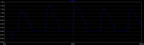
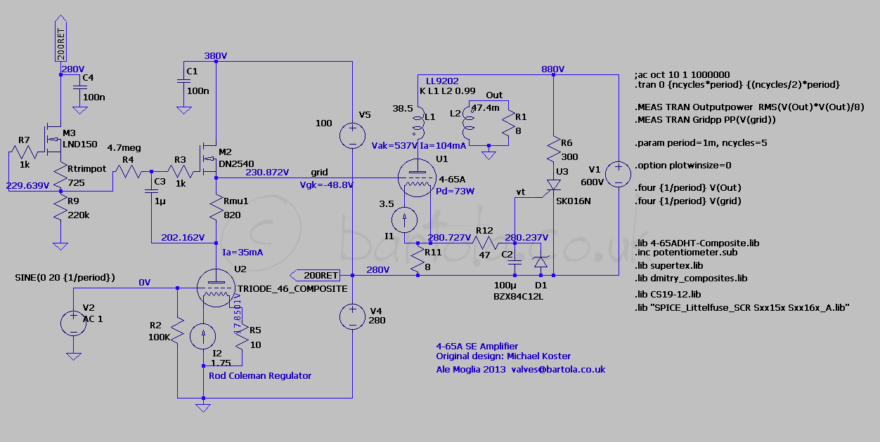
Tested today my 600V raw supply as per diagram below:
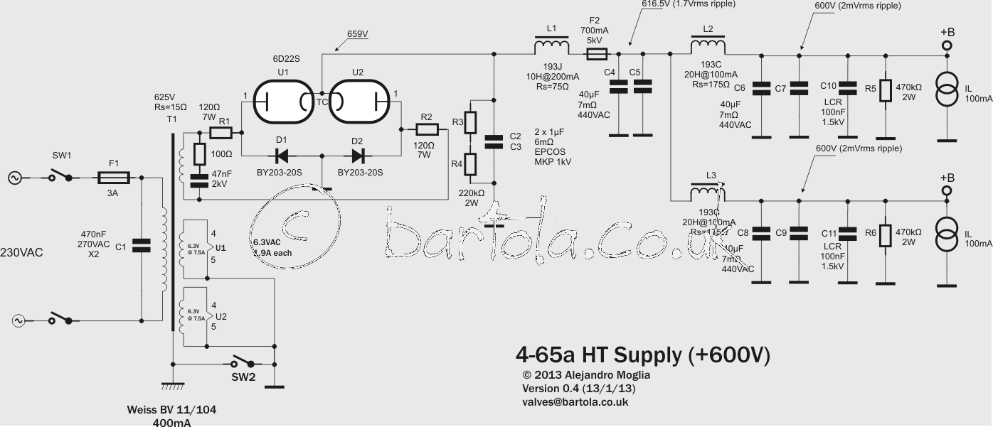
With a VARIAC everything works fine. Now, when applying Mains directly to the supply, I blew up one of the damping resistors R1 as well as shorted D1. Before doing any further tests, do you think I need adding an NTC in the primary to limit the in-rush current?
Also, I know that C1 and C2 in parallel are a bit marginal in terms of the peak voltage that the two caps need to withstand, so far so good but may look at buying a pair extra. They are expensive, though!
Thanks for the steer
Ale
Tested today my 600V raw supply as per diagram below:
With a VARIAC everything works fine. Now, when applying Mains directly to the supply, I blew up one of the damping resistors R1 as well as shorted D1. Before doing any further tests, do you think I need adding an NTC in the primary to limit the in-rush current?
Also, I know that C1 and C2 in parallel are a bit marginal in terms of the peak voltage that the two caps need to withstand, so far so good but may look at buying a pair extra. They are expensive, though!
Thanks for the steer
Ale
Hi euro21,
BY203S-20 has a peak current of 20A, albeit forward current is 250mA. Perhaps the slow start of the 6d22s (more than 30sec) may be the one to blame.
I have these at hand which are rated to 1.2kv @ 5A which are good : http://www.st.com/internet/com/TECHNICAL_RESOURCES/TECHNICAL_LITERATURE/DATASHEET/CD00096465.pdf However, VRRM is 1.2kV
Do you think these will survive or shall I stick two in series?
Ale
Hi Ale,
I don't believe that the 6d22s should be causing any trouble for you. I've used them in a full wave 1250v supply for stereo 845 outputs. The only thing you need to watch out for with them, is internal arcing. They're cheap, so I bought a batch of them, and had to swap out a couple until they did not arc on startup. It seems that once they are run in for a few hours, they should be fine for the long-haul. Also note that you might want to try tying the 6d22s heaters to B+ (their own cathode), but then I believe you must have separate heater windings. As long as you're using the 6d22s, I'd expect that their slow startup means that you don't require the NTC. It looks like a good supply to me. Perhaps try installing a higher power R1?
Cheers,
-MW
I think what you are experiencing is that your gyrator bias point gets unstable when going into A2 operation since you are feeding the voltage reference CCS from the unregulated power supply that provides the peak current in A2. In my design I use V4 (which is the SSHV2 regulator) instead to feed the LND150
Hi Ale,
Just wanted to let you know that I discovered what the problem was. It turned out that the d3a input was going into A2. When I replaced the battery in the grid with a higher voltage, the problem went away. I'm now using a tiny 2.5v NBL type battery.
I also finally managed to take some decent pictures of this amplifier after borrowing my coworker's camera. I posted them over in the tube photos thread: http://www.diyaudio.com/forums/tubes-valves/71300-photo-gallery-463.html#post3328592
Cheers,
-MW
Well, I've decided to take the plunge with an A2 amp, and since I was plunging, I might as well go big.
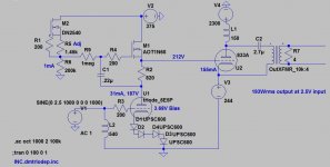
Here's what I plan to build - a near 200W single-ended triode amp using the 833C tube. The attached schematic sims very well in Spice, with FR from 4.5Hz to ~80KHz, -3dB.
Waiting on the needed iron, and for my wife to get over the shock of seeing the 833C tubes when I pulled them out of their boxes...she thinks I'm nuts...
Attachments
Last edited:
Hi Michael,Hi Ale,
Just wanted to let you know that I discovered what the problem was. It turned out that the d3a input was going into A2. When I replaced the battery in the grid with a higher voltage, the problem went away. I'm now using a tiny 2.5v NBL type battery.
I also finally managed to take some decent pictures of this amplifier after borrowing my coworker's camera. I posted them over in the tube photos thread: http://www.diyaudio.com/forums/tubes-valves/71300-photo-gallery-463.html#post3328592
Cheers,
-MW
Great stuff and an impressive finish, it looks fantastic, so well done again!
I guess that the A2 operation of the d3a driver increased the overall distortion so interested to read your comments about changes in the sound of the amp.
Cheers,
Ale
Hi Magz,
Cool! You can also feed M2 from V3, a much more stable source and also will dissipate less power across M2.
I love the 6e5p. If I get the time I will try to measure the distortion at full swing in that configuration. What is the maximum peak signal you need to drive the output valve?
Cheers,
Ale
Cool! You can also feed M2 from V3, a much more stable source and also will dissipate less power across M2.
I love the 6e5p. If I get the time I will try to measure the distortion at full swing in that configuration. What is the maximum peak signal you need to drive the output valve?
Cheers,
Ale
Hi Magz,
Cool! You can also feed M2 from V3, a much more stable source and also will dissipate less power across M2.
I love the 6e5p. If I get the time I will try to measure the distortion at full swing in that configuration. What is the maximum peak signal you need to drive the output valve?
Cheers,
Ale
I'm exploring several options for the power supplies, so that is open for optimization. I'm thinking SSHV2 for V3 and V2, and perhaps I can take the CCS reference power from V3. Lots of options.
The 833 has a high mu (35!) for a power tube, so its drive requirements aren't bad at all. The 6E5P drives it with no problem; at full power the driver is nowhere near clipping.
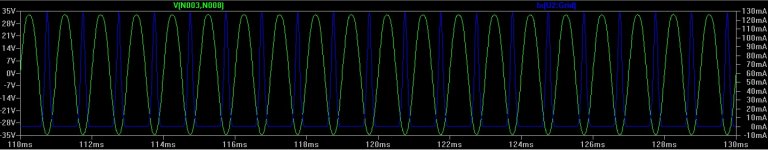
The grid choke really made an improvement in the sims in terms of preventing the grid current pulses from getting back into the input. You can sim it versus a 100k resistor and measure the current across each - with the resistor there are clearly current pulses present (and current across a resistor = voltage you don't want there).
Also, the SiC schottky diodes I'm using for 6E5P bias have very low dynamic resistance - I measured it at 1.3 ohms per diode between 15 and 30mA, so that's only 5.2ohms for the string of four, or about half of one red LED.
.
Last edited:
Hi Magz,
Have a look at the original design from Michael and my design here:
Your V3 (v4 in mine) needs to be as stable as possible. SSHV2 is good, that is what I'm using. V2 (V5 in mine) on the other hand only needs to provide A2 grid current so can be unregulated if the return is the cathode of the output valve.
I wil do the simulations, good tips. However, be aware that the SPICE models are far from being accurate in modelling A2 grid current, so distortion will be probably bigger. You don't want to run the driver with grid current as probably your source will not be prepared for that..
Haven't tried SiC diodes, keen to see how these sound as well, they look perfect candidates!
Cheers,
Ale
Mogliaa,
It looks to me like your V5 is also providing part of the anode current for the driver tube, in conjunction with the PS stacked below it. In any case, the MOSFETs have high PSRR so the supply may be able to be a little rougher than usual. I'll probably regulate both supplies anyway.
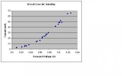
The SiC schottky diodes are very nice, I've used them in preamps before with very good results. They are quiet and give very nice bass response compared to a resistor. I mentioned that I measured them - attached is a plot that I worked up of Vf versus I for the Cree 600V SiC schottky parts.
It looks to me like your V5 is also providing part of the anode current for the driver tube, in conjunction with the PS stacked below it. In any case, the MOSFETs have high PSRR so the supply may be able to be a little rougher than usual. I'll probably regulate both supplies anyway.
The SiC schottky diodes are very nice, I've used them in preamps before with very good results. They are quiet and give very nice bass response compared to a resistor. I mentioned that I measured them - attached is a plot that I worked up of Vf versus I for the Cree 600V SiC schottky parts.
Attachments
I'm working up an 833 amp.....At somewhere around 1500V and 250mA I may even be biased positive
I ran my 833A at 1500 volts (1490 loaded) and 275 mA. Grid voltage was +20 volts. Output power was 212 watts at 5% distortion with a 5K ohm OPT. Driver was a mosfet buffered, CCS loaded 45.
Measured grid current peaks in the 833A were about 250 mA.
The 833A has a rather high plate resistance. This makes the OPT design a challenge. The higher impedance in your sim (10K VS 5K) may even be harder to get right due to the added winding capacitance. The custom built OPT that I had made wasn't quite good enough, and the vendor didn't want to try again even though I was paying for them.
The experiment was here. This was about 5 years ago and I still havent built the amp.....may never happen.
The 833A SE Amp Prototype
Yes, I've seen your work, Tubelab - it was one of my inspirations! I'm going higher in voltage with less current as a starter. Still have a significant amount of grid current even at the higher voltages.
I received my 833C tubes a couple days ago - the pictures don't do them justice, they are HUGE...like a cookie jar. My wife thinks I'm out of my mind...
I'm communicating with a transformer vendor now who has been working on designs for this tube; I won't mention his name yet as he is not planning to produce them for a few more months, but he certainly has the chops to make a good OPT, meaning amorphous cores, low capacitance winding techniques, etc. I'm hoping so...
Yes, I've seen your work
Sorry, I was having a blonde moment.....I recalled a conversation about a month ago about an 833A amp, but I couldn't remember where it was. I didn't think that there could be TWO people going down this route. I am at work now and only have access to the forums via smartphone. I did find it, In the Tubelab forum.
I'm communicating with a transformer vendor now
If anybody can build this transformer, it would be him. I have a small pair of his transformers in a 45 TSE and they are very good. The larger ones are beyond the reach of my financial administrator (wife).
The larger ones are beyond the reach of my financial administrator (wife).
I'll have to cross that bridge when I get to it. I'm envisioning a need for diamonds...
- Home
- Amplifiers
- Tubes / Valves
- Class A2 Direct MOSFET Coupled SE