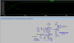
Here's my 833 amp sim. At the output to the 833 grid, -3dB is 2Hz, with a .22uF cap and 1Mohm resistor to ground in the gyrator.
That's low enough in my estimation, and I can fit a nice Duelund CAST on the driver board.
.
That's low enough in my estimation, and I can fit a nice Duelund CAST on the driver board.
.
Attachments
Last edited:
Hello Ale,
I'm adapting a variant of this scheme to my 833C 'Midlife Crisis" Amp. My custom OPTs and HV chokes just arrived at the airport in a 92kG crate according to the tracking data (yay!).
Just one question: why such a large cap in the gyrator/mu follower? You have a corner frequency of 0.03Hz when combined with the 4.7M +220K resistors. You could easily drop that to 0.22uF or even lower. Smaller caps usually sound better provided they achieve the required corner frequency, IMO, and they are cheaper, too!
Hi Magz,
Looking forward to seeing your results on the 833C! Very exciting. I personally think that the 6e5p is a great choice as a driver.
Thanks for spotting out the cap value. I went back through my notes and found that originally calculated a 100nF cap for 1Hz-3dB corner but somehow I wrote down 1uF. It happens that I have some 1uF caps around so I just went ahead without checking this again! The Amp -3dB corner is primarily driven by the output stage LF response which should be around 7Hz. Haven't measured it yet though. Of course using a lower cap is better from a sound perspective so will look at buying some to test the difference.
A 220nF will provide 0.5Hz corner. The 1uF one gives a -3dB point of 0.15Hz which is completely unnecessary.
At the moment I have at hand for testing: 1) Mundorf MCap EVO SilverGold Oil and 2) Obligato Premium. Both are 1u ones. Will need to buy some good 100nF ones and try them and compare!
Cheers,
Ale
Glad to be of help, Ale.
FYI, I posted a little LTSpice distortion study on the Midlife Crisis thread, looking at the distortion spectrum of my sim amp in class A1 versus A2. I thought the results were interesting, and applicable here as well.
http://www.diyaudio.com/forums/tube...-crisis-my-833c-amp-build-32.html#post3608682
In a nutshell, predominant 2H distortion in A1 vs predominant 3H and higher distortion in A2.
Hi Magz,
The THD response will be very much dependent on the model you are using for your valves. Specially whether these have a good approximation on the grid current and yes, it will be higher on odd harmonics in class A2. The challenge is also to fit the anode curves with positive grid bias, as this will also impact the THD levels as curves get shrunk at higher grid positive voltages. My tracer has its limitations but I'm closely to build my version of the uTracer which allows you to trace positive grid bias curves very easily (and safely).
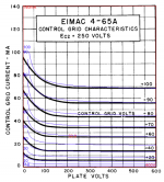
I refined my 4-65a DHT model to better match the grid current as attached.
The THD response will be very much dependent on the model you are using for your valves. Specially whether these have a good approximation on the grid current and yes, it will be higher on odd harmonics in class A2. The challenge is also to fit the anode curves with positive grid bias, as this will also impact the THD levels as curves get shrunk at higher grid positive voltages. My tracer has its limitations but I'm closely to build my version of the uTracer which allows you to trace positive grid bias curves very easily (and safely).
I refined my 4-65a DHT model to better match the grid current as attached.
Attachments
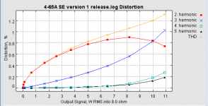
Good to see that your experimental data has the same trends as my simulation data, in terms of THD, and the fall off of 2H and rise of 3H and higher as you go deeper into class A2.
Of course the absolute amounts of distortion need to be taken with a measure of caution in the sim since there is no accounting for imperfect voltage sources, tube models and the like, but the trend data is interesting.
Of course the absolute amounts of distortion need to be taken with a measure of caution in the sim since there is no accounting for imperfect voltage sources, tube models and the like, but the trend data is interesting.
Last edited:
I need to optimise the 600V HT power supply. Currently have a 4A T fuse and works well with in-rush when supply is cold. If I turn off/on again then the fuse blows. Obviously 4A is too much as primary current shouldn't be more than 0.8-1A (230V and 200VA),so fuse is not of any good use then.
Thought about adding an NTC (B57211P0409M3*1)on the primary. I found this 4R 3W mains rated one:
http://www.epcos.com/inf/50/db/icl_12/NTC_ICL_P11.pdf
Do you think this would be a good solution to limit inrush current?
Thanks
Ale
Thought about adding an NTC (B57211P0409M3*1)on the primary. I found this 4R 3W mains rated one:
http://www.epcos.com/inf/50/db/icl_12/NTC_ICL_P11.pdf
Do you think this would be a good solution to limit inrush current?
Thanks
Ale
I need to optimise the 600V HT power supply. Currently have a 4A T fuse and works well with in-rush when supply is cold. If I turn off/on again then the fuse blows. Obviously 4A is too much as primary current shouldn't be more than 0.8-1A (230V and 200VA),so fuse is not of any good use then.
Thought about adding an NTC (B57211P0409M3*1)on the primary. I found this 4R 3W mains rated one:
http://www.epcos.com/inf/50/db/icl_12/NTC_ICL_P11.pdf
Do you think this would be a good solution to limit inrush current?
Thanks
Ale
Ale,
What I did was to use NTC for initial start, and then bypass the NTC after a small delay of time. I still have to use a 1.5A fuse for B+ on each channel, though. I think if you quickly turn off the amp and then back on, the NTC on my amp probably will still be bypassed because the timing capacitor has not had time to discharge.
-MW
Speaking of ridiculously low impedances, 2N7000, LEDs, resistors: jokes, all of them. TL431 is adjustable and comes in at an ohm or two, and is priced similar to a 2N7000 or red LED.
If anybody feels like trying the TL431 cathode bias, like I did - don't do it. The TL431 is noisy (bandgap reference inside) and that noise gets amplified by the tube.
After some months of playing with the 4-65a, I couldn't resist from testing the 814 in triode mode. Results are very encouraging as this lovely transmitting tetrode can withstand +550V in triode mode.
http://www.bartola.co.uk/valves/2013/11/23/814-se-a2-amplifier/
The sound is great and I'm inclined to say that I prefer this from the 4-65a so far. It still has a fantastic bass and dynamic response whilst the treble is there. Very detailed and warm tone as well. I'm enjoying this and will keep it for some time now before the next tweak.
Thanks to Paul LeClerq for continuously pushing me to try this valve!
Cheers
Ale
Hi all,
After some time I finally run some proper measurements on my 814-SE amplifier. I nearly blown it away (twice) by trying to do excessive power sweeps and also did some speaker measurements. Thanks to the crowbar protection, all remained ok. A real challenge for a DC-coupled amplifier.
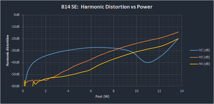
The case was proven that the 814 in triode mode is an outstanding valve. Here is the THD of the amp:
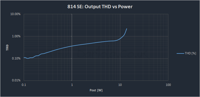
It operates mostly in class A2 (above 3W) and harmonic profile is quite nice for this type of amp:
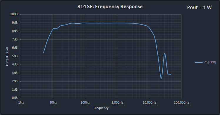
The response of the 46 driver is fantastic (i.e. up to 48kHz) however the output stage is slightly disappointing as -3dB is around 17kHz. I assume that the OT capacitance is bigger than expected as a byproduct of a reasonable primary inductance to achieve good LF response for an iron gapped at 100mA. Not easy to achieve in an amp. The sound is fantastic anyway and I don't perceive any loss in HF - at least on my ears")
Naturally anode to anode feedback (a la Schade) could be something to explore to improve BW, but is a test for later in the future:
If you are interested in further details of this test, you can read it here: 814 SE Amplifier: measurements | Bartola Valves
Cheers
Ale
After some time I finally run some proper measurements on my 814-SE amplifier. I nearly blown it away (twice) by trying to do excessive power sweeps and also did some speaker measurements. Thanks to the crowbar protection, all remained ok. A real challenge for a DC-coupled amplifier.
The case was proven that the 814 in triode mode is an outstanding valve. Here is the THD of the amp:
It operates mostly in class A2 (above 3W) and harmonic profile is quite nice for this type of amp:
The response of the 46 driver is fantastic (i.e. up to 48kHz) however the output stage is slightly disappointing as -3dB is around 17kHz. I assume that the OT capacitance is bigger than expected as a byproduct of a reasonable primary inductance to achieve good LF response for an iron gapped at 100mA. Not easy to achieve in an amp. The sound is fantastic anyway and I don't perceive any loss in HF - at least on my ears
Naturally anode to anode feedback (a la Schade) could be something to explore to improve BW, but is a test for later in the future:
If you are interested in further details of this test, you can read it here: 814 SE Amplifier: measurements | Bartola Valves
Cheers
Ale
After hundreds of hour of operation of my 814 SE amp, I experienced the first fault on the power supply. It wasn't unexpected as I had some warning signs of the inevitable end of the 6D22S damper valves. A couple of times I experienced some brief arcing when switching the supply at low temperatures. As the arcing was only for a fraction of a second and then the supply worked fine, I never bothered to change the dampers.
Last night it was rather chilly in my sitting room after the unusual warm temperatures in September/October. When I turned the 600V supply on, one of the dampers produced an arc and the dampening series resistor (100R 7W wirewound) nearly melted before dying. It was cherry red. The hybrid bridge has a sturdy STTH512 UF rectifier which can do 5A continuous. The 100R resistor acted as the fuse and I immediately switched off the supply.
This morning I repaired the supply and all went back to normal after refitting a new pair of 6D22S. I burned them in for 30min with the filaments on only. I then applied the top cap and tested them on the bench before connecting the supply to the system.
Anyone experienced faulty/arcing 6D22S before? Can I blame the rectifiers or can be anything else to consider?
cheers
Ale
Well, not sure whether it was an uneven cathode coating that weakened the 6D22S but I suspect that once an arc strikes, the rectifier is damaged.
I think George (Tubelab) recommended adding a series diode to help taming the arc, I rather use the series resistor to use it as a fuse!
It seems to work fine now...fingers crossed
Ale
I think George (Tubelab) recommended adding a series diode to help taming the arc, I rather use the series resistor to use it as a fuse!
It seems to work fine now...fingers crossed
Ale
I have just bought back two massive Sowter OPT's (8456) for SE with 8K primary that I used to have more than fifteen years ago but never used. These were originally intended for the Svetlana SV811-10. Specs 15W class A, 100mA. Sowter size Q (almost 10kg per piece)
Thinking about making this sort of amplifier using mogliaa's gyrator boards. 814 output tube perhaps, but other ideas are welcome.
Thinking about making this sort of amplifier using mogliaa's gyrator boards. 814 output tube perhaps, but other ideas are welcome.
Last edited:
I have a question about the stacked supplies for this kind of design. Is it possible to arrange the current loops as shown below? Assume there's filtering/regulation where needed, of course (simplified so I can wrap my head around this).

Or would it be preferred to stack the supply for the output stage with the current return directly to its own winding?

I would be going after much lower voltages here and am thinking that several identical windings/voltages would be a little simpler (and more scalable) if they can be stacked like the first example.
Or would it be preferred to stack the supply for the output stage with the current return directly to its own winding?
I would be going after much lower voltages here and am thinking that several identical windings/voltages would be a little simpler (and more scalable) if they can be stacked like the first example.
Is the data set used in that plot still in your file?Mogliaa,
It looks to me like your V5 is also providing part of the anode current for the driver tube, in conjunction with the PS stacked below it. In any case, the MOSFETs have high PSRR so the supply may be able to be a little rougher than usual. I'll probably regulate both supplies anyway.
The SiC schottky diodes are very nice, I've used them in preamps before with very good results. They are quiet and give very nice bass response compared to a resistor. I mentioned that I measured them - attached is a plot that I worked up of Vf versus I for the Cree 600V SiC schottky parts.
If so I'd like a copy. THX in advance.
- Home
- Amplifiers
- Tubes / Valves
- Class A2 Direct MOSFET Coupled SE