I would be grateful if at some point you had the time to dig out your notes. Having now read the whole thread, I don't think the info is in here somewhere. Post number 15 may be hinting at the potential issue, but I couldn't find a reply.I used a Tektronix current probe to measure the AC and DC screen current. I could look in my notes for the exact figures but suffice to say neither idle g2 current nor average g2 current at full signal results in anywhere near max dissipation. If you do read the whole thread the measurement may be documented in some post near the beginning. If not I can retrieve it..
It had not occurred to me to run these tubes in traditional triode strapped configuration, though admittedly I have no experience with the 4-65A in particular. Quite interested in the actual DC parameters at the operating point.
High g2 current is drawn when the plate voltage is below g2 voltage. With plate and g2 strapped together this doesn't happen. The monograph "Beam Power Tubes" by O.H. Schade provides a good technical explanation.
Thanks, though I feel I have the basics covered. Most of my experience just happens to be at RF in more traditional configurations, like GG or standard (beam) tetrode with a few KV on the anode.
")
That would have been my next question. With upwards of 1.5KV(peak) between g1 and g2, I'd worry about internal flash overs, particularly as the tubes age. I have experienced the phenomenon in a traditional all-glass transmitting tube at about these voltages, and that was even with a normal g1 driven tetrode setup. Wonder if the DC resistance of the OPT plus the MOSFET body diode is enough to deal with the issue?Likewise the g2 maximum voltage spec can also be exceeded when plate and g2 are connected together.
- Frank.
I have a couple extra heat dissipating caps for the 4-65A if you're having trouble finding them.
Michael
Thanks for the offer.. I know of a few sources but if you are wanting someone to take them off your hands, I would be happy to oblige. I'm in a mandatory waiting period now that I've apparently killed two of the 10m90's. I wired up the second channel and was powering everything up, measuring the bias voltage when it just all of a sudden went to supply voltage and would not adjust. The other channel remained fine though. So... next time I'll have to add in the protection zeners
Not quite sure what happened but gate to source on both the devices is a lot lower in R than the working devices.I've been listening to the amp on my main system now, playing not longer than a song or two for fear of melting glass. I probably sucked some life out of those tubes by not using the dissipating caps. I'm going to order a pr of the caps tomorrow from RF parts. The first thing that struck me about the sound of the amp was how lightning fast and immediate it is. I have not tried a DC coupled amp before, but I imagine it might be something like this. The bass is very tight and well defined, good highs and good detail. The 4-65a sounds amazingly powerful when you give it some volume. I would say that it even sounds more powerful than the 845 amp I previously built, but may not be a fair comparison since the 845 was IT coupled and not DC coupled. Quite amazing for a tube that's somewhere in size between a typical power audio tube and a transmitter like the 845.
In comparison:
The only things that seems to be lacking from the d3a -> 45 amp is some subtlety, tone and soundstage depth. Now with those parts "lacking" they are almost certainly some subtle colorations that the type 45 brought. I can do without the slightly loose and rounder mid and lower bass of the 45, and can bring back some tone with different coupling caps and resistors in the mix. The DC filament supply I'm currently using for the 4-65a is also barely adequate and will be replaced by a supply from Rod Coleman.
In conclusion I think I like this amp well enough to make it into my full-time amplifier in my main system. It will be in monoblock configuration with two decks - one for power supply and one for signal. I have a few PCB layouts to send out too: raw filament supplies, mu-follower, and a Salas hv regulator for the 4-65a cathode supply.
Michael K - if you have not tried grid bias on your input tubes using a battery supply, I think you should give it a try sometime. You have to isolate the DC, but you might like the trade-off. I personally find it better than all other types of biasing the input stage. You get a great amount more detail and dynamics, without sacrificing clarity, smoothness or freq response that are common compromises of other types of bias. To be fair though I must try biasing with a tl431 or jfet, as I have not done this yet.
For those of you not familiar with the mu-follower, I found this link to be very informative: Mu Stage Philosophy © 1993 Alan Kimmel
Regards,
-Michael Woods
I've been enjoying the amp this past week, but only after I swapped out the coupling cap to the mu-follower. I was using an old ERO cap here before and it didn't sound so hot, making me wonder if I need to rethink things. I thought what the heck, might as well swap in the better coupling caps even though I didn't think it was as critical in this circuit. It made an enormous difference, so better to try a few things if you haven't already. I have Ampohm aluminum PIO's in there now.
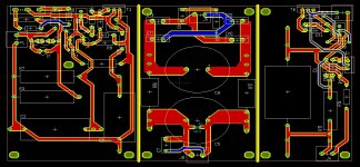
Here's an image of the boards. Left to right it is the SalasHV reg, then filament supply, and last the mu-follower. It's only the second board I have drawn, so I am sure there is room for improvement.
Still waiting to hear back about cost of the iron from Tribute.
I hope more people try out this circuit, too!
-Michael Woods
Attachments
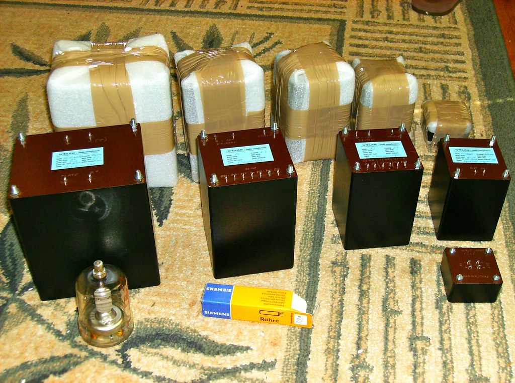
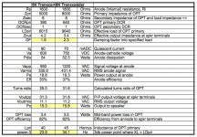
The iron for my amplifiers finally arrived from Tribute. This is a monoblock set. From largest to smallest they are:
9k pri, 6R sec, amorphous C core OPT.
Power transformer with 100mA secondaries - 750v, 800v, 850v secondaries with center tap.
Power transformer with three 65mA secondaries - 1x 280v and 2x 90v.
Amorphous core choke - 100mA.
Cobalt amorphous core input transformer 1:1.2
I also have the PCB's back from Olimex and tested the Rod Coleman heater supply for the 4-65a.
Not sure yet if I will just build up the entire monoblock amps, or do a bit more prototyping with the new parts on-hand. Probably a bit of both. I figure that if I end up not liking the sound, I can still use these transformers in a GM70 amp.
Hi everyone,
I'm looking with real interest to build an 811a SE with Michael's circuit design. Albeit I haven't seen many 811a circuits out there, comments in general are very positive.
I'm interested to hear some comments on the sound and also any recommendations on the OT.
Thanks
Ale
I'm looking with real interest to build an 811a SE with Michael's circuit design. Albeit I haven't seen many 811a circuits out there, comments in general are very positive.
I'm interested to hear some comments on the sound and also any recommendations on the OT.
Thanks
Ale
I would be grateful if at some point you had the time to dig out your notes. Having now read the whole thread, I don't think the info is in here somewhere. Post number 15 may be hinting at the potential issue, but I couldn't find a reply.
It had not occurred to me to run these tubes in traditional triode strapped configuration, though admittedly I have no experience with the 4-65A in particular. Quite interested in the actual DC parameters at the operating point.
Thanks, though I feel I have the basics covered. Most of my experience just happens to be at RF in more traditional configurations, like GG or standard (beam) tetrode with a few KV on the anode.
That would have been my next question. With upwards of 1.5KV(peak) between g1 and g2, I'd worry about internal flash overs, particularly as the tubes age. I have experienced the phenomenon in a traditional all-glass transmitting tube at about these voltages, and that was even with a normal g1 driven tetrode setup. Wonder if the DC resistance of the OPT plus the MOSFET body diode is enough to deal with the issue?
- Frank.
Hi Frank,
Better late than never?
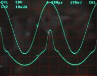
Here's a trace of the g2 current from the Meteor amp. Top trace is the G1 voltage from the driver at 270V pk-pk and bottom trace is the g2 current at 10 mV/division. At zero signal, the g2 current is about 9 ma (at ~700V). This would result in about 6 watts g2 dissipation, well under the 10W data sheet maximum.
Attachments
Hi everyone,
I'm looking with real interest to build an 811a SE with Michael's circuit design. Albeit I haven't seen many 811a circuits out there, comments in general are very positive.
I'm interested to hear some comments on the sound and also any recommendations on the OT.
Thanks
Ale
The relatively high plate resistance of the 811A would result in a low speaker damping factor if used in the zero feedback Meteor circuit.
Also, the 811A will only need about 30 volts peak-peak for full output in a SE circuit.
For the 811A I would use the same technique as for the 100th and other high resistance power grid triodes, with local current mode feedback to a pentode driver. Basically a "Schade" feedback circuit but with the Meteor power grid driver between the driver plate and power tube grid.
Hi Michael,
Thanks for the response. I need to sit down and study the circuit In detail. I'm really keen to use a 46 as a driver with the MOSFET gyrator as per your circuit. Given that the 811a only needs 40Vpp and that also I have a 26 preamp, I may be able to get away with the 46 triode-strapped? What do you think about this?
Thanks for the help!
Ale
Slowly getting there.
I'm still coming along with my project, just at very slow pace. I am taking somewhat of an opposite approach to MichaelK, since I'll be using 4 large chassis in a dual mono config. I've spent a huge amount of time on layout, chassis design and even purpose built racks/stands for the amps. Tested the salasHV reg plus mu-follower fixed voltage board this morning, everything working as expected. I am trying the 1N60 device in cascode. What's not in this test setup that will be in production is the additional stacked supply that feeds the A2 current. I like having the two adjustable voltages (salas plus A2 board), since this will give me the ability to adjust the current of both the first and second stages individually. The A2 board would adjust the anode voltage of my d3a, while the salas on the cathode will adjust the 6-45a.
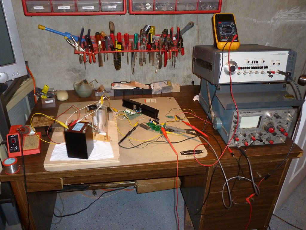
I'm still coming along with my project, just at very slow pace. I am taking somewhat of an opposite approach to MichaelK, since I'll be using 4 large chassis in a dual mono config. I've spent a huge amount of time on layout, chassis design and even purpose built racks/stands for the amps. Tested the salasHV reg plus mu-follower fixed voltage board this morning, everything working as expected. I am trying the 1N60 device in cascode. What's not in this test setup that will be in production is the additional stacked supply that feeds the A2 current. I like having the two adjustable voltages (salas plus A2 board), since this will give me the ability to adjust the current of both the first and second stages individually. The A2 board would adjust the anode voltage of my d3a, while the salas on the cathode will adjust the 6-45a.
I got this from Dave Slagle
Michael
Hi Michael,
I've got a set of 4-65a NOS, so this will be my next project once curve tracer is completed
Can you please send me the spice model you are using?
Thanks
Ale
Hi Ale,
I don't have the spice model; you'll need to ask Dave Slagle. I just used the triode curves he published.
I'm thinking about a curve tracer as well. That's a recurring topic here...
If the curve tracer could measure all of the electrode currents, with enough electrode voltage combinations, a "simple" curve fitter/interpolator could drive a very realistic spice model.
Cheers,
Michael
Last edited:
Hi Michael,
Thanks. Unfortunately my curve tracer (still in a breadboard) can measure up to 300V and no positive grid curves.
I don't know Dave Slagle so a bit lost there...
I could try to create a new one based on your plotted curves from Spice, but thought it was a waste of effort if someone has already done it
Cheers,
Ale
Hi Michael,
Can you run the 4-65a without the Eimac top connector i.e. with a standard top connector with no heatsink? Given the op point is not at max PD, would this be possible?
Thanks
Ale
The 4-65A needs to run over 50 watts with a red glowing anode for the best tube life. At this dissipation, I assume that the heat dissipating connector is needed.
They come up on ebay regularly, but it does take a little while to find a matching pair. You can also remove the 5/16 cap, leaving the thick anode wire, and attach a dissipating cap sized for the wire. I have both types and can supply you with a pair if needed.
Cheers,
Michael
Hi Michael,
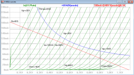
I used the curves from Dave you posted earlier and managed to create a SPICE model using Dmitri's tool. See model below. I think is nearly there...
http://www.bartola.co.uk/valves/Valves_and_Hi-Fi_audio/Entries/2012/4/22_4-65a_Triode_curves_files/shapeimage_2.png
What is the operating point you ended up using?
Thanks
Ale
Last edited:
Hi Michael,
I used the curves from Dave you posted earlier and managed to create a SPICE model using Dmitri's tool. See model below. I think is nearly there...
http://www.bartola.co.uk/valves/Valves_and_Hi-Fi_audio/Entries/2012/4/22_4-65a_Triode_curves_files/shapeimage_2.png
What is the operating point you ended up using?
Thanks
Ale
With an 8K OPT, I used 750V and 70mA. That was just enough to get the orange color you see on my anode
Attachments
Thanks Michael! that's a lot of good insight.With an 8K OPT, I used 750V and 70mA. That was just enough to get the orange color you see on my anode
I'm waiting for the arrival of a pair of nice LL9202 gapped at 100mA. I'm not really looking at maximising every single watt here, so am a happy bunny with 10-12W. My power output valve supply will be limited to around 600V, so looking at LL9202 with Rp=600 ohms max (need to check primary winding combination based on target Np:Ns wanted) should be around Va=540V @100mA.
The LL9202 can do either Zaa=6.5K or 11K for this purpose, what would be your recommendation based on your tests?
Thanks
Ale
- Home
- Amplifiers
- Tubes / Valves
- Class A2 Direct MOSFET Coupled SE