Hi Michael
I just saw this thread. A very interesting amp
I'm very attracted to the lineraity, looks and price of the 4-65A
Would an OPT that I have for an 845 be ok:
Primary 10 Kohm
Secondary 4-8-16
Max DC 100 ma
Primary
Inductance 50 H?
and how would it be with the EL34 as driver?
Thanks
I just saw this thread. A very interesting amp
I'm very attracted to the lineraity, looks and price of the 4-65A
Would an OPT that I have for an 845 be ok:
Primary 10 Kohm
Secondary 4-8-16
Max DC 100 ma
Primary
Inductance 50 H?
and how would it be with the EL34 as driver?
Thanks
Hi Michael
I just saw this thread. A very interesting amp
I'm very attracted to the lineraity, looks and price of the 4-65A
Would an OPT that I have for an 845 be ok:
Primary 10 Kohm
Secondary 4-8-16
Max DC 100 ma
Primary
Inductance 50 H?
and how would it be with the EL34 as driver?
Thanks
Hi,
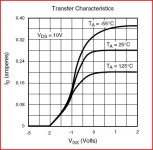
I think a 10K OPT would be great for the non-feedback triode circuit in post #1. I've been thinking of the triode wired 4-65 as a poor man's 845 ;-) Similar plate resistance and mu factor and similar looking curves.
EL34 as a driver? The triode-wired 4-65A will need a lot of grid drive voltage. The driver tube will thus need to provide a lot of gain, which is why I used a high gain triode. The EL34 in pentode connection with a 5K ohm load resistor or thereabouts would provide enough gain and the 5K output resistance should work OK with the MOSFET circuit. The load resistor will dissipate up to 2 Watts at full signal. A triode wired 12HL7 or 12GN7 would give you a lot of gain also. 6GK5 may be worth a try also.
Keep us posted...
Cheers,
Michael
Michael -
I am looking at your 35tg version (M2) with the single supply and wondering how the Vbias supply would look. Is this just an independently regulated and adjustable supply? I would guess that is the case and it needs to be around 130V. I am sort of trying to combine your M2 and the Meteor together so that we're looking at a single plate supply for a pentode driving a tetrode (4-65) with Schade feedback. I wonder if the Vbias supply and the screen for the 4-65 (250V) could be combined. I can at least tell that the Vbias would only be biasing the mosfet and not providing current too, as in the Meteor version.
I've been listening to the 717a AC coupled to globe 45 with battery bias for 717a's grid. It sounds so good that I haven't wanted to touch my system! BTW the globes over the ST 45 made a huge difference I never would have imagined. Anyway, I took it apart tonight so that I can try type 10 as the output and also finally work on the A2 circuit.
I'm deciding to stick with the cheap OPT for now and see if I can get the A2 circuit at all close to the 45 as far as enjoyability goes! The 45 is still under-powered for my setup and preference.
Michael -
I am looking at your 35tg version (M2) with the single supply and wondering how the Vbias supply would look. Is this just an independently regulated and adjustable supply? I would guess that is the case and it needs to be around 130V. I am sort of trying to combine your M2 and the Meteor together so that we're looking at a single plate supply for a pentode driving a tetrode (4-65) with Schade feedback. I wonder if the Vbias supply and the screen for the 4-65 (250V) could be combined. I can at least tell that the Vbias would only be biasing the mosfet and not providing current too, as in the Meteor version.
I've been listening to the 717a AC coupled to globe 45 with battery bias for 717a's grid. It sounds so good that I haven't wanted to touch my system! BTW the globes over the ST 45 made a huge difference I never would have imagined. Anyway, I took it apart tonight so that I can try type 10 as the output and also finally work on the A2 circuit.
I'm deciding to stick with the cheap OPT for now and see if I can get the A2 circuit at all close to the 45 as far as enjoyability goes! The 45 is still under-powered for my setup and preference.
What you want to do sounds reasonable. I think the 717A would be possible as the input tube; is this what you're thinking?
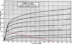
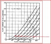
Here's a load line for the 4-65A. This is a really good way to go for plate efficiency. 25W at the plate output for about 58W dissipation.
I'll think about the power supply scheme a little more.
Cheers,
Michael
Attachments
What you want to do sounds reasonable. I think the 717A would be possible as the input tube; is this what you're thinking?
Here's a load line for the 4-65A. This is a really good way to go for plate efficiency. 25W at the plate output for about 58W dissipation.
I'll think about the power supply scheme a little more.
Cheers,
Michael
I am thinking that I should try the 717a but also d3a, c3g and 6cl6.
I've been kicking around at this idea too. Some of the values aren't correct and the mosfet is missing its bias, but you should get the idea. I'm working on the voicing of the first two stages for now. It can end up being any number of different tubes for the first two stages, but last stage should stay relatively the same. Ohh... and the diodes on the filament supplies probably look a bit strange. That's just a little thing I am going to try out in theory to heat the filament more evenly from a DC supply. I will be using the new supplies from Rod Coleman for at least the two last stages.
-Michael Woods
-Michael Woods
Attachments
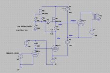
Actually this is a better example of what I was thinking. It's still conceptual, but at least the tubes are biased now ") I have not separated the grid load and anode load supplies here just for simplicity.
I have not separated the grid load and anode load supplies here just for simplicity.
I don't like the large 10k resistor that's used to drop B+ to the input tube in order to bias the next stage. Any suggestions on my options there? Should I try using a regulator in this position or change the way the next stage is biased? I'm welcome to any criticism!
-Michael Woods
I have not separated the grid load and anode load supplies here just for simplicity.I don't like the large 10k resistor that's used to drop B+ to the input tube in order to bias the next stage. Any suggestions on my options there? Should I try using a regulator in this position or change the way the next stage is biased? I'm welcome to any criticism!
-Michael Woods
Attachments
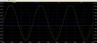
I hope this thread is not permanently extinct! I did a few more sims to use three stages. Here's what the plot is showing:
V(n002) This is the p-p voltage of the 211 output tube
Ix(U2:Grid) Current that is drawn from 211 while in A2 operation
I(V1) Current that is supplied by the grid bias supply.
I(V2) Current that is supplied by the driver/211 cathode supply.
The amp begins to clip only at the output and is only limited by 211 plate dissipation rating. It's interesting to see how the grid current supply is isolated and supplying a huge amount of current to the 211.
Not sure I'd want to try to implement something with so many power supplies! One thing I can't figure out with my sim, is that when I place the mosfet's protection zener, the voltage regulator breaks down and I am unable to bias the mu-follower.
Attachments
Output tube current
Hi
I have a question about the output tube current:
Is it better to put high voltage/low current
or low voltage/high current.
I ask this for tube life.
If i look at the 211 datasheet, filament is 10V 3.25A
tube current max is 175ma
For the 845, same filament, max tube current is 125ma.
I know with high voltage/low current, the tube output will
have a higher resistance.
I am a bit confused about that!
Regards
From what I noticed, most power tubes are operated to 50-75% of the maximum rated dissipation. In general, a more conservative operating point will usually extend the life of the tube. However, the 4-65A(Max PD is 65W) is an exception; it needs to operate with a cherry red plate (55W or so) in order to getter properly. If you ran it conservatively, the tube will probably go gassy and die...
I hope this thread is not permanently extinct! I did a few more sims to use three stages. Here's what the plot is showing:
V(n002) This is the p-p voltage of the 211 output tube
Ix(U2:Grid) Current that is drawn from 211 while in A2 operation
I(V1) Current that is supplied by the grid bias supply.
I(V2) Current that is supplied by the driver/211 cathode supply.
The amp begins to clip only at the output and is only limited by 211 plate dissipation rating. It's interesting to see how the grid current supply is isolated and supplying a huge amount of current to the 211.
Not sure I'd want to try to implement something with so many power supplies! One thing I can't figure out with my sim, is that when I place the mosfet's protection zener, the voltage regulator breaks down and I am unable to bias the mu-follower.
That's all working as expected.
Which polarity did you place the zener?
It sounds like you may have had the zener forward biased.
Why 3 stages? I would have thought the D3a in triode can swing more than enough voltage for the 211 and have a low enough plate resistance to work well in the circuit.
Cheers,
Michael
Attachments
Here's the 417a load line showing about 260V P-P plate swing. I get up to 300V P-P by driving the 417a a little into A2 with my signal generator.
The dotted line shows the effect of finite MOSFET gfs which causes a little grid current to "leak through" to the driver plate. Selecting the MOSFET source R value can minimize this.
Cheers,
Michael
The dotted line shows the effect of finite MOSFET gfs which causes a little grid current to "leak through" to the driver plate. Selecting the MOSFET source R value can minimize this.
Cheers,
Michael
Attachments
I hope this thread is not permanently extinct! I did a few more sims to use three stages. Here's what the plot is showing:
V(n002) This is the p-p voltage of the 211 output tube
Ix(U2:Grid) Current that is drawn from 211 while in A2 operation
I(V1) Current that is supplied by the grid bias supply.
I(V2) Current that is supplied by the driver/211 cathode supply.
The amp begins to clip only at the output and is only limited by 211 plate dissipation rating. It's interesting to see how the grid current supply is isolated and supplying a huge amount of current to the 211.
Not sure I'd want to try to implement something with so many power supplies! One thing I can't figure out with my sim, is that when I place the mosfet's protection zener, the voltage regulator breaks down and I am unable to bias the mu-follower.
Are you planning to use 14K OPT primary impedance? The new Lundahl high impedance OPT would be an awesome combination with the 211.
I would go with D3a in triode, 417a, or 6C45pi in a 2 stage straight Meteor circuit unless there is some reason for the 3rd stage I'm not able to grok.
Cheers,
Michael
Are you planning to use 14K OPT primary impedance? The new Lundahl high impedance OPT would be an awesome combination with the 211.
I would go with D3a in triode, 417a, or 6C45pi in a 2 stage straight Meteor circuit unless there is some reason for the 3rd stage I'm not able to grok.
Cheers,
Michael
Michael - I mostly just simmed the 3 stages with the 211 to see how it would be done. I'm not necessarily going to use three stages. I'm currently listening to a 2-stage d3a into type 45 amp that sounds phenomenal. I might end up comparing d3a->4-65a vs three stages. Do you happen to have a spice model of the 4-65a?
With the protection zener I tried both polarities and different voltages. All of them result in defeating the voltage regulation.
The zener is connected between source pin and gate pin, right?
Try two 15V zener diodes with the cathodes connected together then.
I don't have a spice model for the 4-65A but Dave Slagle has something that generates triode curves; maybe just from the tetrode curves.
Michael
The zener is connected between source pin and gate pin, right?
Try two 15V zener diodes with the cathodes connected together then.
I don't have a spice model for the 4-65A but Dave Slagle has something that generates triode curves; maybe just from the tetrode curves.
Michael
Michael - Thanks! Two zeners back to back does the trick! BTW, were you, or someone else thinking of releasing a kit for such a mu circuit? Just curious. I think the trick with that would be finding the correct voltages for the two power supplies and their intended bias points.
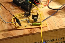
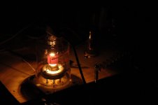
I tried the circuit out - d3a to 4-65a with mu-follower. Doing a single channel and using the IXCY 10m90s. Mostly just using parts that I had on-hand. I'll have to pickup the heat dissipating anode caps before running stereo on my system. Good test though! All the voltages came out as expected and it was neat to tune the bias for color on the plate.
Attachments
Sorry for being late to the party, only just discovered this thread.
Did any of you try to measure the screen grid current in idle? Haven't read every post, so you very well may have.
Usually you would strap g2 to g1 and not the anode, when triode strapping members of this family of tubes. With g2 to the anode, zero bias and Va at 750V I wonder if the screen grid might be running *way* over maximum allowed dissipation, which is 10W.
I used to run a triode strapped 4-250A at 375W out, g2 to g1, though that was at 28MHz class AB2.
Sorry for being late to the party, only just discovered this thread.
Did any of you try to measure the screen grid current in idle? Haven't read every post, so you very well may have.
Usually you would strap g2 to g1 and not the anode, when triode strapping members of this family of tubes. With g2 to the anode, zero bias and Va at 750V I wonder if the screen grid might be running *way* over maximum allowed dissipation, which is 10W.
I used to run a triode strapped 4-250A at 375W out, g2 to g1, though that was at 28MHz class AB2.
I used a Tektronix current probe to measure the AC and DC screen current. I could look in my notes for the exact figures but suffice to say neither idle g2 current nor average g2 current at full signal results in anywhere near max dissipation. If you do read the whole thread the measurement may be documented in some post near the beginning. If not I can retrieve it..
High g2 current is drawn when the plate voltage is below g2 voltage. With plate and g2 strapped together this doesn't happen. The monograph "Beam Power Tubes" by O.H. Schade provides a good technical explanation.
Likewise the g2 maximum voltage spec can also be exceeded when plate and g2 are connected together.
Cheers,
Michael
I tried the circuit out - d3a to 4-65a with mu-follower. Doing a single channel and using the IXCY 10m90s. Mostly just using parts that I had on-hand. I'll have to pickup the heat dissipating anode caps before running stereo on my system. Good test though! All the voltages came out as expected and it was neat to tune the bias for color on the plate.
I have a couple extra heat dissipating caps for the 4-65A if you're having trouble finding them.
Michael
- Home
- Amplifiers
- Tubes / Valves
- Class A2 Direct MOSFET Coupled SE