What about a sustained short-circuit? (long enough to blow OPS power fuses). Don't you want VAS currents or BE junction currents to be limited? I'm really trying to make my amp be able to handle a sustained short-circuit, even after the OPS fuses have blown. I'd hate to lose expensive parts and / or PCB tracks...
Once speaker relay (MOSFET SSR) disengages due to over current it stays off. I use a random phase opto triac for this. You have to power cycle the amp to enable it again. I guess if it trips again,you have a serious problem.
The nx-Amp trips at about 14A and the e-Anp at 30 to 40 Amps. The sx amp only has fuses in the rail. You can short it out and it pops the fuses and is ready to go again as soon as you replace them. I am using 1382/1302 on +- 22V rails so they can really deliver a lot of current.
"Andrew, I'm really impressed by your protection scheme.
It's what I wanted to do in the 90's but was too expensive."
It's not my idea Richard - I just refined it a bit.
We are very lucky nowadays - there are some amazing a Trench mosfets out there with ultra low Rdson and still very reasonable.
It's what I wanted to do in the 90's but was too expensive."
It's not my idea Richard - I just refined it a bit.
We are very lucky nowadays - there are some amazing a Trench mosfets out there with ultra low Rdson and still very reasonable.
Hmm will have to take a look at your solutionsOnce speaker relay (MOSFET SSR) disengages due to over current it stays off. I use a random phase opto triac for this. You have to power cycle the amp to enable it again. I guess if it trips again,you have a serious problem.
The nx-Amp trips at about 14A and the e-Anp at 30 to 40 Amps. The sx amp only has fuses in the rail. You can short it out and it pops the fuses and is ready to go again as soon as you replace them. I am using 1382/1302 on +- 22V rails so they can really deliver a lot of current.
") I'm bent on using HEC inside the GNFB, and the drivers can pass a serious current when shorting out the output, this current would smoke any diode array clamps at the output FET gates. I must limit it if I want to be sure fuses go first. It does have a side benefit though, when the HEC is overdriven, it won't oscillate when coming out of clip/overload.
I'm bent on using HEC inside the GNFB, and the drivers can pass a serious current when shorting out the output, this current would smoke any diode array clamps at the output FET gates. I must limit it if I want to be sure fuses go first. It does have a side benefit though, when the HEC is overdriven, it won't oscillate when coming out of clip/overload.Fully characterized seems improbable to me but yes, using combinations of different waves at different levels tells us plenty. I'm not ready to throw my ears out just yetBonsai said:See Self et al for a discussion on why music signals are not a special case - an amp can be fully characterized from just sine and square wave testing.
Mr. Cordell said:
"I'm still a big believer in having a Zobel on the output node of the amplifier ahead of the L-R series network."
Does anyone have an schematic example of this topology?
Kris, almost all amps presented in Solid State are with this kind of a zobel and R//L at the output.
Fully characterized seems improbable to me but yes, using combinations of different waves at different levels tells us plenty. I'm not ready to throw my ears out just yet
Agree - never throw the ears out - the most important instrument!
In the end we're all bickering about THD, Slewrates and what not more to ultimately please our ears =)Agree - never throw the ears out - the most important instrument!
Slew rate is only applicable during overload, which shouldn't happen in the first place. It may be weakly related to behavior at listening levels.
At listening levels I think what you're looking for is step response. A small square wave (100mV at output or less) will show you the amp's normal behavior without driving it into slewing.
At normal listening levels small-signal step response is directly related to the frequency response and phase behavior. However as a visual test I think it is a bit more sensitive because frequency response can appear flat while the step response shows overshoot or other anomalies.
As for what perceptual qualities it affects, I am not sure but I would think it matters for perception of spatial cues, for instance reproducing echoes correctly and being able to tell how far away the performer is, etc.
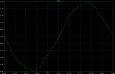
You mean something like this? The picture shows a 1KHz sine with a 5KHz square imposed. The sine equals about 1W into 8R, the square/sine ratio I set to get ~100mV squares as you say.
This is with a 12dB/Oct 730KHz input filter though. When omitting the input filter, it goes into slew with a slight overshoot of about one cycle of ringing (up peak, much smaller down peak, settled, ring period approx 2MHz).
This is with a 12dB/Oct 730KHz input filter though. When omitting the input filter, it goes into slew with a slight overshoot of about one cycle of ringing (up peak, much smaller down peak, settled, ring period approx 2MHz).
Attachments
This is akin to Prof. Cherry's recommended output network which I briefly mentioned in Dave Zan's "Middlebrook GFT probe" thread.
My own brief SPICE sims suggests this is a better way to go than the normal Zobel + Thiele that Self describes. However, I don't have 'real life' experience of this method. Your experience encourages me to look further.
Much of my poor SPICE efforts have been trying to replicate my Jurassic 'real life' experiences. I'm rather impressed by LTspice. It usually gives sensible results if you have good models like Bob Cordell's, and if you realise PCB tracks have evil Inductance & Capacitance too.
I'm loath to recommend stuff that I haven't tested in some form in 'real life'.
After the initial design using analysis & PM/GM, I tend to use .TRANS to pick up problems and then switch back to PM/GM for the specific trouble cases. You can look at overload behaviour too.
I say more on my "TPC vs TMC vs pure Cherry" thread. Again I stress its all stuff you should do in 'real life' too. In SPICE world, you can do loadsa stuff like this without releasing the Holy Smoke.
For the big 'real life' guitar speaker, things seem to happen just above the bass resonance but before the impedance flattens off and becomes 'resistive'. My guess is the speaker impedance is falling fast and capacitive in this range.
Andrew, I'm really impressed by your protection scheme.
It's what I wanted to do in the 90's but was too expensive.
Are you referring to the series R-L network as a "Thiele" network. Not sure I've seen this before, and not sure it is appropriate. I am very familiar with Thiele's work that he did on the topic, but the series netwrok consisting of parallel R and L had been around long before that work. Thiel's was a specific approach to output networks that happened to include a series R-L netwrok.
Am I wrong about this?
Cheers,
Bob
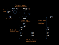
Here is an example of a "complete" output network. I've also added the Tian Probe to show how it's connected.
Yes, excellent. One further point. I sometimes recommend a "distributed" on-board Zobel consisting of several smaller Zobels close to each output pair when multi-pair output stages are used. This enables the use of smaller Zobel components and non-inductive metal-oxide or metal-film resistors. Fast output transistors like to have the Zobels close-by. This approach does not necessarily take up much more PCB space.
Cheers,
Bob
You mean something like this? The picture shows a 1KHz sine with a 5KHz square imposed. The sine equals about 1W into 8R, the square/sine ratio I set to get ~100mV squares as you say.
This is with a 12dB/Oct 730KHz input filter though. When omitting the input filter, it goes into slew with a slight overshoot of about one cycle of ringing (up peak, much smaller down peak, settled, ring period approx 2MHz).
Run the low freq signal at say 100 Hz and the HF at 10 or 20 kHz at c. 100 mV.
The LF signal should swing to about 90 % of the rails. What it does is excel use all the device parametrics, while the small HF signal looks for loop stability across the full operating range.
Run the low freq signal at say 100 Hz and the HF at 10 or 20 kHz at c. 100 mV.
The LF signal should swing to about 90 % of the rails. What it does is excel use all the device parametrics, while the small HF signal looks for loop stability across the full operating range.
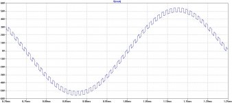
I think that 100Hz sin and 20kHz square is to extreme, it takes to long to run simulation.
Here is 2kHz sin at almost full power and 20kHz square +-100mV from my lateral MOSFET 200W amp.
Attachments
Hi dadodI think that 100Hz sin and 20kHz square is to extreme, it takes to long to run simulation.
Here is 2kHz sin at almost full power and 20kHz square +-100mV from my lateral MOSFET 200W amp.
When I look at the graph, the squares seem to have peak-to-peak value of about 5V instead of .2? Also, is that without input filter?- Home
- Amplifiers
- Solid State
- CFA Topology Audio Amplifiers