Hi Bob, thanks for your insight on this, it makes me feel like it's better to keep the 22n cap on-board right after the inductor and still keep a standard Zobel at the terminal.Four thoughts:
1) I am always paranoid about resonances and the like at high frequencies. Just a straight 0.022 cap to ground at the output terminals makes some sense, but if that is all there is I worry about opportunities for resonance against the wiring back to the board or the speaker cable - or it causing some "tuning" of the speaker cable transmission line. For that reason, it still might be wise to parallel that capacitor with a Zobel to assure good damping at that node. I am assuming that the cap and Zobel are right across the output terminals.
Cheers,
Bob
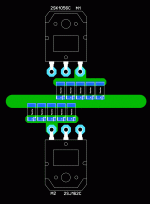
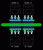
The symmetry nut in me would offset the bottom transistors so the emitters (and resistors) line up perfectlyIs this an acceptable starting point?
Edit: Or create a bit more vertical space to guide the emitter trace towards lined up resistors and keep the transistors also lined up.
Last edited:
The symmetry nut in me would offset the bottom transistors so the emitters (and resistors) line up perfectly
Edit: Or create a bit more vertical space to guide the emitter trace towards lined up resistors and keep the transistors also lined up.
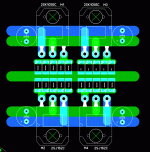
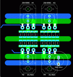
Lika Dis Here
I would like to add a big piece of solid copper #12 AWG would be nice right down the middle of the output trace...
Attachments
Last edited:
Does anyone remember an post or thread that talked about "listening to the capacitors" of the output transistors. It is like the need for LARGE caps next to the output transistors..
It's better to have distributed electrolytic caps close to the each output transistor than only two large ones. 220uF is a good value for those capacitors.
Quantum discount weee! I'd gonna need 20pcs that way.It's better to have distributed electrolytic caps close to the each output transistor than only two large ones. 220uF is a good value for those capacitors.
Hi Bob, thanks for your insight on this, it makes me feel like it's better to keep the 22n cap on-board right after the inductor and still keep a standard Zobel at the terminal.
My leaning would have been to put the 22nF at the speaker terminals in parallel with the speaker-side Zobel, but it probably does not make much difference.
Cheers,
Bob
I suppose so, for the intention of this capacitor, to provide this minimum capacitive load it wouldn't matter if there would be additional wire inductance in series with the output network L. But maybe the wire resistance may make this load less 'pure'? Not that that would be bad for the purpose. You're most likely right in that it doesn't really matter.My leaning would have been to put the 22nF at the speaker terminals in parallel with the speaker-side Zobel, but it probably does not make much difference.
Cheers,
Bob
I use gEDA on Linux and it's easy. Maybe you just need better software?
On the topic of the Zobel:
Many people seem to assume that the larger the capacitor the more likely to cause oscillation. This is not true. Oscillation can occur with capacitive load 470pF and up. Testing a range of capacitors is a good idea.
Shorting the speaker terminals with a 22nF cap to force capacitance to a minimum is a good idea, and may help amps that are particularly sensitive to the load.
What worries me is if someone plays a 96KHz sine out of their soundcard, what happens to the Zobel? Before the Zobel fries, how much power is being dissipated in the outputs? What if you accidentally press the wrong button on your signal generator and fry your zobel?
Can we make a zobel that is effective and that also can withstand the entire output range of modern soundcards without needing bulky resistors?
Last edited:
Why not make the ground and rail traces perfectly parallel, directly on top of one another? Then turn the caps 90 degrees. Much less radiated magnetic field, and much less inductance as well.
Yes.
THx-RNMarsh
Last edited:
As for frying Zobels, when I was testing my MF80 project, it wasn't untill I briefly tested with 1MHz and above test waves its Zobel began to release the holy smoke (I like that term). With the 200KHz test pattern, either sine or square, the Zobel held up just fine. It was a 10R/3W, 47nF combo. Rated output power 80W into 4 ohms. So the voltage swing wasn't very large. I would assume with a larger swing I'd have to use 5W resistors I think.What worries me is if someone plays a 96KHz sine out of their soundcard, what happens to the Zobel? Before the Zobel fries, how much power is being dissipated in the outputs? What if you accidentally press the wrong button on your signal generator and fry your zobel?
- Home
- Amplifiers
- Solid State
- CFA Topology Audio Amplifiers


