I suggest you check LF stability wih your zillion dB/decade servo .. or at least design your PCB so you can revert to a simple 6dB/8ve roll-off.
That filter has already been built by others on the forum. putting it in front
of the integrator will only do good things.
If you see a B$ circuit , or one in error (dangerous) , feel free to "shoot it down"
or offer improvements. If not , you have contributed absolutely nothing.
(good thing we are moderated )
OS
ostripper, I have not seen this zillion dB/decade servo of yours but I'm just nervous of such beasts.That filter has already been built by others on the forum. putting it in front of the integrator will only do good things.
If you see a B$ circuit , or one in error (dangerous) , feel free to "shoot it down"
or offer improvements. If not , you have contributed absolutely nothing.
If you give me a link to this impressive beast, I'll be able to do more than just 'suggest'.
Have the 'built' versions of this filter been in front of a servo integrator in a 'real life' amp?
I'm confident your filter is stable in itself .. but putting it in a servo loop may be a problem.
Last edited:
Edmond, do you have a link to the additional circuitry is necessary to ensure a decent behavior at overdrive conditions you mention in that link
Hi Richard,
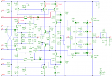
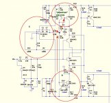
Below you see the complete schematic of the MCP amp. The signal path (one half) of the clamp circuitry is marked red. A similar clamp (of the PMP amp) is described here.
It wouldn't be nice if I reveal who designed that amp. I only can tell it's an 30 years old and well known design. It uses separate power supplies for the front-end and OPS. The front-end does have a (brute force) clamp, but if the power supply for the front-end is a little to high (or the power supply for the OPS a little too low), this clamp is ineffective and recovery from overload looks horrible.and also the subsequent one with bad overload recovery?
edit: Therefore I prefer a clamp that gets activated when one of the drivers of the OPS is on the verge of saturation. This way the clamp works always and doesn't depend on the voltages of the power supplies.
Cheers, E.
Attachments
Last edited:
ostripper, I have not seen this zillion dB/decade servo of yours but I'm just nervous of such beasts.
If you give me a link to this impressive beast, I'll be able to do more than just 'suggest'.
Have the 'built' versions of this filter been in front of a servo integrator in a 'real life' amp?
I'm confident your filter is stable in itself .. but putting it in a servo loop may be a problem.
The original -
Spice Component and Circuit Modeling and Simulation
The thread ... http://www.diyaudio.com/forums/chip-amps/107246-dc-servo-question.html
I just used the filter part , NO inversions , 10 cycle at 20Hz( near complete) correction.
I lowered the -3db to .5hz and control the input pair CCS's with the servo OP.
It performs brilliantly with many op-amp macro's.
OS
Last edited:
Srvo ideas --
More DC-Servo concepts/idea for CFA -- via current-mirrors and current-sources. These will help for your own project:
View attachment servo 3.pdf
View attachment servo 4.pdf
Thx-RNMarsh
More DC-Servo concepts/idea for CFA -- via current-mirrors and current-sources. These will help for your own project:
View attachment servo 3.pdf
View attachment servo 4.pdf
Thx-RNMarsh
Last edited:
More DC-Servo concepts/idea for CFA -- via current-mirrors and current-sources. These will help for your own project:
View attachment 395279
View attachment 395280
Thx-RNMarsh
Servo 3 is a cool addition that I see commonly on OEM's .
Would #4 not make for "unbalanced operation" ? maybe I will try #4 balanced
(miib).
Kgrlee set me on the right path ...
a filter w/ too steep a rolloff fails to integrate the high harmonic content of a SW/pulse.
It did not cause a
"catastropic" simulation , but a far from optimal one ..
even with LPF/integrater (order) swapped.
OS
3 +4 =

CFA amp takes on the PSSR + other better characteristics of the VFA op-amp
while still being a "bloody crude speed demon CFA"
Even killed the op-amp , main CFA will go class B with 5V offset ,
but still operate. Main amp bias can now be adjusted from the single 2Q w/ 1 trimmer.
Was a gift ? Thanx !!
PS - being asymmetrically sourced (like a VFA) w/ stock CCS one side and
precision op-amp controlled mirror the other .... the "silver bullet".
OS
Attachments
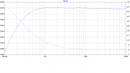
Thanks for this OS. The filter is used quite sparingly in Tom's circuit and the effects are not disastrous.
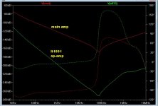
However, Tom neglects one of the simplest stability tests .. frequency response.
GooteeServoOriginal.png is the response of the circuit as shown on his webpage and downloaded. The effect can be seen but is less than 1dB
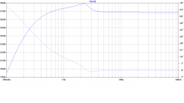
GooteeServo800mHzfilter.png has the 'DC Accurate 60dB/decade filter' lowered to 0.8Hz by making C10 & 12 2u2 from 1u. The 'feature' is now 1dB.
This all depends on exact details of the filter, integrator & the power amp. The whole shebang is a feedback LF filter and needs to be considered as such.
You can have fun finding combinations which are unstable
but you should at least check the frequency response of the combination you use.The time response of the whole thing .. ie how the system responds to offsets & 'DC pulses' etc is entirely described by the frequency response.
eg the simple 'integrator only servo' has exactly the same behaviour as a single capacitor deciding the LF cos both have exactly the same frequency response
Attachments
3 +4 =
CFA amp takes on the PSSR + other better characteristics of the VFA op-amp
while still being a "bloody crude speed demon CFA"
Even killed the op-amp , main CFA will go class B with 5V offset ,
but still operate. Main amp bias can now be adjusted from the single 2Q w/ 1 trimmer.
Was a gift ? Thanx !!
PS - being asymmetrically sourced (like a VFA) w/ stock CCS one side and
precision op-amp controlled mirror the other .... the "silver bullet".
OS
Last edited:
eg the simple 'integrator only servo' has exactly the same behaviour as a single capacitor deciding the LF cos both have exactly the same frequency response
Pulse tests are very revealing of many issues (eg power supply behavior etc). Yes, good test for servo behavior.
Check group delay at 10-20hz. Want no group-delay issues in audio range from a servo filter.
Thx-RNMarsh
Last edited:
Pulse tests are very revealing of many issues (eg power supply behavior etc). Yes, good test for servo behavior.
Check group delay at 10-20hz. Want no group-delay issues in audio range from a servo filter.
Thx-RNMarsh
Checked that along with my group delay- AOK ! (8uS !)
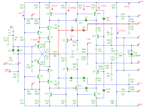
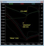
(below 1) is the "famous , controversial" feedback amp (VSSA / whatever) ...
"A" (circled) is the only "real" current source. "P" is the mirrored "phantom"
source ... in the middle is the CFA pair.
Looks like a "blameless" except for the CFA pair (instead of an LTP) in the middle.
The real current source is set to 1.6ma , it's 'tail" is set to about the same...
mirrored through Q3/4 for the positive "phantom CCS".
"B" is a summing junction for the servo+CCS current that the mirror "see's".
Add the servo's few nA to the main CCS's reference current and that is what
the phantom CM "CCS" will be.
__ Remove the servo ,
the amp performs the same ! -88 to -150 db PSRR across the audio spectrum.
There will be a little offset , you could replace the op-amp with a trimmer and
add a few 100mV's to zero out (at R16). The "effect" is the CCS topology , not
the op-amp.
The servo is a nice addition (if you want it) , you could also add the trimmer to its non-inverting
input for manual zeroing. PLUS ! it will also perfectly "track" any changes to
the CCS's current to always have no offset.
Another added side effect is even LOWER PSRR and lower THD 20. With
the servo , CCS current stays within .0001ma . (without .0005ma)
This thing is WAY ahead of the VSSA in just about all aspects.
The "NX" diamond could be tweaked like this , too.
Very nice "silver bullet" , Thanx .. RN !
EDIT - I think I found out why I have lower THD ... my LF open loop gain increased 17db ??
Could this be the doing of the CM ?? (like in a VFA)
OS
Attachments
Last edited:
Tried that ... not much better performance. here I get 99% with 4
semi's instead of 8.
I did go all the way (8) as you suggest - good idea BTW !
Did you notice the UGLF bode plot ? It looks like a VFA/CFA "hybrid" !
I was still able to get 200+ V/uS and my UGP to 2mhz ..
A lot of extra gain at 20 -30K ... all the CFA pluses.
It still is a CFA.
But , the "plateau " on the bode doesn't extend to as high a frequency and the LF gain is MUCH higher. Strange , but it works ....
I might try different Re's for the mirror and/or a wilson CM.
PS -I want to fit this on a tiny IPS board for my "slewmaster"
True with the extra semis, The way i did it was to make a lower voltage central supply, like a LED-based 12 V shunt, then use that as the backside of the input stage (you'll need the 12V for your servo anyway). Then I use the 8 semis for the central house-keeping and servo supply. This takes the PSSR to unbelievable heights and maintains all of the CFA goodies.
Checked that along with my group delay- AOK ! (8uS !)
(below 1) is the "famous , controversial" feedback amp (VSSA / whatever) ...
"A" (circled) is the only "real" current source. "P" is the mirrored "phantom"
source ... in the middle is the CFA pair.
Looks like a "blameless" except for the CFA pair (instead of an LTP) in the middle.
The servo is a nice addition (if you want it) ,
EDIT - I think I found out why I have lower THD ... my LF open loop gain increased 17db ??
Could this be the doing of the CM ?? (like in a VFA)
OS
Good implementation of the concept - and keeping the parts count down is a plus, too.
Thx-RNMarsh
This takes the PSSR to unbelievable heights and maintains all of the CFA goodies.
Thx-RNMarsh
Good implementation of the concept - and keeping the parts count down is a plus, too.
Thx-RNMarsh
Thank you .
One thing that must be considered is that there IS still a "tradeoff".
The increased LF loop gain + better PSRR has a price ... lower 20K
available gain and a slightly slower amp. This can be compensated by
raising the UGP or by increasing Re on the CM.
Both the CSS and CM are hi-Z , but the CM is higher. One would think
this would unbalance the input pair in some manner (miib's IS balanced -2 CM's).
I checked this... and not more than a few PPM between the 2 designs.
PS - You did know VFA/CFA would merge , RN . Did you design/build
this already .... and dropped the hint just to see how fast we would
catch on (up) ?
OS
With low currents (like below a few mA) you can cascode the mirrors with a Jfet, then you reach Tohm territory. If you mirror current over to the VAS, then you take away any influence that rail modulation may have on current scaling in the rail resistors. I know this is increased component count and that the improvements are only of academic interest. But it's fun to observe that most distortion mechanisms are due to non ideal behavior of current sources. with VAS mirrors you can get to sub ppm at 20 KHz full tilt.
Checked that along with my group delay- AOK ! (8uS !)
(below 1) is the "famous , controversial" feedback amp (VSSA / whatever) ...
"A" (circled) is the only "real" current source. "P" is the mirrored "phantom"
source ... in the middle is the CFA pair.
Looks like a "blameless" except for the CFA pair (instead of an LTP) in the middle.
.
.
.
Could this be the doing of the CM ?? (like in a VFA)
OS
Very nice idea!
- Home
- Amplifiers
- Solid State
- CFA Topology Audio Amplifiers