Just a simple little ol' integrator for a phono amp !! ??
THIS is a power amp ... and I'm going overboard (anal)...
Nothing but the best for our beloved solid state.
OS
It's a servo balancing the mirrors (that what it is
) and a floating CCS (and (yes) a simple 1-amp servo)
Last edited:
Simple circuits are good with good housekeeping. Taking out the negative influence of the servo is major. Now if you run a lateral output without VBE, thermal issues in the input stage is enough to make it run away. With your output-triple and dual VBE you control it elsewhere. sorry to derail this not my intention of turning it into a housekeeping subject.
I wonder if this is an issue with the Lateral VSSA ?
(I just put out the catnip)
OS
It's a servo balancing the mirrors (that what it is
In the Accuphase M9 power amp, their CFA's servo does same via current-mirror.
Thx-RNMarsh
Last edited:
I've rewritten the CFA vs VFA doc and posted it up on my site - link below.
Thank you for that, a lot of work and useful information.
I have a few minor contributions.
Fig 1 on the R. The text for the IPS should be "Q6 and Q7" not "Q5 and Q6"
Fig 3. The colours for the Uncompensated OLG, the Compensated OLG, the Uncompensated CLG and the Compensated CLG are all the same.
Makes it very hard to decipher, especially the phase.
And a bit more serious
Fig 8. The caption is that the VFA and "CFA" are compensated for the same PM at their respective ULGF.
This is not what the plot seems to show. The PM for the VFA is about 80 while for the "CFA" looks about 50 or just a trace less.
This is not as fair as the caption states and I suspect this makes a substantial difference to the results.
On the models used in the update to my document, the feedback resistors on the VFA were lowered to the same values as the CFA since it was pointed out that this did not allow an apples to apples comparison. It made virtually no difference.
...
I also tried MIC on the VFA, but did not include the results - the doc is already 24 pages long. The results were not substantially different...
Could you please post the new ASC? I would like check a few points.
The difference between the VFA and "CFA" is more that I would have expected from my earlier sims.
Educational to see where the differences lie, it's not easy to do a fair comparison.
And the MIC comparison occurred to me too, still want to see the results.
Best wishes
David
I just checked my own comparison and found it wasn't quite fair either.
But I had accidentally favoured the "CFA", my mistakes are unbiased
Last edited:
Irritatingly, about 12, depending on the details, the way I was doing it.Thanks for explanation (and I agree with your reasoning). Next point: how many additional BJTs are required for a constant product CMCL?
Cheers, E.
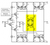
The circuit below illustrates the idea. in this version, VAS current gain = hFE*2/3 and VAS quiescent current = 4 * input stage quiescent current. One could obviously rationalise the mirrors to save a few transistors. I just drew it like this, with same-value components throughout to make the mirror ratios obvious at a glance.
A number of refinements could be added but I wanted to keep this as simple as possible because:
a) Simple = easy to understand
b) I drew it manually with a paint program, which was even more painstaking and time-consuming than I expected.
Similarly, I didn't bother adding an output stage. The VAS drives the output and feedback network directly. This does demonstrate the current-on demand nature of the VAS quite nicely though.
The one I was fiddling with in the sim was a bit different. It had VAS current gain = hFE and a few extra resistors in the yellow box which allow it's gain to be set to the desired value, even with mismatched transistors. Note that emitter resistors can't be used with the transistors in the yellow box as it relies on the exponential Ic/Vbe relationship to work properly.
Attachments
Thanks. For designs that want to exploit the current-on-demand property, the emitter resistors of the input devices can be chosen so that the transconductance of one device risesas the other falls, so the total transconductance remains almost constant. It's the same basic mechanism as a typical class AB output stage, so one can use similar analyses e.g. Doug Self's "birdwing" diagrams.Your point about current on demand is a good one. In a CFA, when the demanded current from the input stage exceeds twice the idle current, I think the "other" side of the input stage cuts off and delivers no more transconductance if I am not mistaken.
Not quite sure what you meant there, but I agree that if the VAS has a constant, linear current gain, then the current on demand property carries over from the input stage to the VAS. Only trouble is that the VAS gain is normally low (3 in your circuit, if I followed it right). I really must get hold of Bob's book and find out what his "magic trick" is.If you mirror and scale the current into the VAS then you get the current on demand property in that section too.
P.S. My non-ownership isn't a dis of Bob's work - I don't own any books devoted to audio electronics.
The one I was fiddling with in the sim was a bit different. It had VAS current gain = hFE and a few extra resistors in the yellow box which allow it's gain to be set to the desired value, even with mismatched transistors.
A very practical feature especially for DIY building.
-RNM
I wonder if this is an issue with the Lateral VSSA ?
(I just put out the catnip)
OS
Why do you think that the bias circuit is made with an Reference (LM431 series) instead of a resistor or bias cicuit with transistors? A step of 12 to around 15mA is a lot to handle with an standard bias circuit Even with an CFP pair as bias it is hard to get a stable bias within a lets say 10mV (10mV/(0.2R*2) => 25mA/transistor rail in change with an RE of 0.2R )
- Sonny
If you mirror and scale the current into the VAS then you get the current on demand property in that section too. That also have the benefit that you have means of controlling the VAS current better as it can thermally compensated in the driving CCS.
Without actually discussing it, Michael and I use the exact same principle to control the VAS current.
It is the one and only way to do it, as I see it. You no longer have the problem with rising current (or falling VBE voltage 2.3mV/degrees) as a function of rising temperature in the VAS transistor.
This way you get just as stable VAS idle current as in the blameless design of D.Self... In d. self design is the current controlled by a current sink/source at the opposite rail.
- Sonny
Thank you for that, a lot of work and useful information.
I have a few minor contributions.
Fig 1 on the R. The text for the IPS should be "Q6 and Q7" not "Q5 and Q6"
Fig 3. The colours for the Uncompensated OLG, the Compensated OLG, the Uncompensated CLG and the Compensated CLG are all the same.
Makes it very hard to decipher, especially the phase.
And a bit more serious
Fig 8. The caption is that the VFA and "CFA" are compensated for the same PM at their respective ULGF.
This is not what the plot seems to show. The PM for the VFA is about 80 while for the "CFA" looks about 50 or just a trace less.
This is not as fair as the caption states and I suspect this makes a substantial difference to the results.
Could you please post the new ASC? I would like check a few points.
The difference between the VFA and "CFA" is more that I would have expected from my earlier sims.
Educational to see where the differences lie, it's not easy to do a fair comparison.
And the MIC comparison occurred to me too, still want to see the results.
Best wishes
David
I just checked my own comparison and found it wasn't quite fair either.
But I had accidentally favoured the "CFA", my mistakes are unbiased
I am travelling this week so it will have to wait a few days. It's probably a labeling error - I am scrupiously fair.
Thanks for pointing these out.
I just took a quick look. Fig 8 is confusing and I will reword the text around it. Both amplifiers have around 80 deg PM at the ULGF of the VFA. The ULGF of the CFA is still around an octave higher.
The models will have to wait until tonight or Thursday before I can post them IP - I will probably just put them up on my website so they can be downloaded.
The models will have to wait until tonight or Thursday before I can post them IP - I will probably just put them up on my website so they can be downloaded.
... I will reword the text around it...
I never doubted that you try to do fair comparisons and I think the text describes a fairer comparison than the data shows.
So I would rather have the data to match that text than alter the text to match the data.
Equalise the PM and compare what ULGF is achievable.
That is probably the less convenient option for you but I can check it myself once I have the ASC.
I look forward to that when convenient for you, no hurry.
Best wishes
David
Agreed. Let's also not forget about gain margin. Equalize the phase margin for comparison, but only if both designs then exhibit adequate gain margin. Certainly nothing less than 6dB of gain margin.
Cheers,
Bob
there are more questions about "fair" comparisons
more loop gain shaping is possible with just a few added parts
such as series R for the Miller C, feedback lead C or even R+C ead/lag, degeneration bypass at VAS, diff pair or the mirror - which really requires dgen for noise performance if nothing else
if these an other "simple" gain shaping tricks are applied to known, well behaved small signal transistor gain circuit poles of either amp then I think you will find both CFA and VFA end up limited by the output Q, allowance for thier phase, Ft variations over output I,V, load Z
and we keep getting repetition of debunked or irrelevant "CFA advantages", stated as assumed fact – makes it hard to find the “progress” some think has been made
...Equalize the phase margin for comparison, but only if both designs then exhibit adequate gain margin...
Of course. I think 6dB is bare minimum too. I have actually become a bit more conservative there.
...more loop gain shaping is possible with just a few added parts...
Absolutely! That is exactly what I had in mind, hence one of the reasons to request to ASC.
I did notice the lack of emitter resistors in the CM but didn't want to comment until I checked the effect.
Otherwise it looks like a quibble.
if these an other "simple" gain shaping tricks are applied to known, well behaved small signal transistor gain circuit poles of either amp then I think you will find both CFA and VFA end up limited by the output Q...
My expectation also. Unfortunately I have little data on actual excess phase (strictly defined) in transistors.
A Tektronix test set up accurate to about 200 MHz is on the buy list.
Best wishes
David
Last edited:
" and we keep getting repetition of debunked or irrelevant "CFA advantages", stated as assumed fact – makes it hard to find the “progress” some think has been made "
I think it cuts both ways. Theres been plenty of claims from both sides that are unsubstantiated ranging from simple misinformation because people have not played with some models right through to complete subjective nonsense.
However, if you can use 'tricks' shape a VFA's loop response . . . you can do the same with a CFA.
you . . . can make a CFA high(er) loop gain
. . . make a CFA lower distortion
. . . make a CFA with high PSRR
. . . make a VFA with higher SR
. . . MIC, TMC, TPC, OIC all bring benefits to VFA's . . . you can use them with CFA as well
etc etc.
CFA is a viable amplifier topology thats been around in audio power amplifiers for decades so no amount of dissing it from anybody here is going to make it go away.
For those (of either pursuasion) that keep making garbage claims: just ignore 'em!
Last edited:
In the Accuphase M9 power amp, their CFA's servo does same via current-mirror.
Thx-RNMarsh
Richard which amp is this, arent you mistaking with pioneer perhaps. I dont recall such a accuphase model.
As far as I can remember accuphase always made use of a servo to the inverting input, sometimes fet other bjt and low cost in the past. In the newer models where they use the diamond buffers and vas in totem pole [ Im not sure what else to call the topology] the servo is linked to the non inverted input. So far NE5532 has been used exclusively with this topolgy.
Its obvious they dont feel the servo is such an important factor.
I have near all their models schematics or access to them so Ill be able to verify if the servo to current mirror scheme was ever used.
- Home
- Amplifiers
- Solid State
- CFA Topology Audio Amplifiers