John already has taken care of this in his new schematic from post @7092:Hi Kolby,
How do you plan to compensate this phase difference?
The window has been moved to WS=1 zone by using a 74LVC80 (U7) to reset the counter and enable the window. Left data is loaded first while WS=0 and put through the 32 bit delay line. When WS=1 the R channel data is clocked out together with the delayed and now aligned L channel data.
request for I2S to LR alternating serial trailing data schematic
John,
you are very generous
I have I2S source which like to Input to NPC SM584X digital filter
would you please advise on how to correct your schematic In a way to do I2S to SM5842 digital filter Input, etc. how to convert I2S to LR alternating serial data
regards
John,
you are very generous
I have I2S source which like to Input to NPC SM584X digital filter
would you please advise on how to correct your schematic In a way to do I2S to SM5842 digital filter Input, etc. how to convert I2S to LR alternating serial data
regards
I attached a schematic diagram of an I2S to Simultaneous converter for the TDA1541A.
The circuit performs following functions:
- Identify and invert MSB within the serial data stream.
- Delay the left channel data in order to align it with the R channel data.
- Create a 16 bit window for clock and data output signals.
Timing diagram is added at the bottom.
The circuit can be built with logic building blocks like 74HC, 74 AHC, 74LV, 74LVC.
If U13 is a problem one can combine two 74HC86 XOR gates instead. One output goes to one input of the other XOR gate, we now have an XOR gate with 3 inputs and one output. The 74LVC1G386 is available in SOT32-6 housing:
http://www.ti.com/lit/ds/symlink/sn74lvc1g386.pdf
Depending on logic building block properties the circuit can work on voltages between 2V4 and 5V. I recommend to use 2V4 ... 3V3 supply voltage.
Connections:
I2S,
DI = D
WSI = WS
BCKI = BCK
Simultaneous,
OB/TWC (pin 27) connects to -5V to put the TDA1541A in simultaneous mode.
DOL connects to pin 3
DOR connects to pin 4
BCKO connects to pin 2
LE connects to pin 1
LE determines the exact moment of output latching, output latching occurs at the 0 -> 1 transition (TDA1541A set to simultaneous mode).
BCK clocks in the data on the 1 -> 0 transition (TDA1541A set to simultaneous mode).
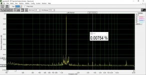
Here is the spectrum of 1198Hz -3dBfs RMS sine (full scale peak) with using an ADUM3160 based USB isolator before the Weilang 24-bit USB-to-I2S/SPDIF card. RI/V = 100R. No much difference really.I repeated my previous FFT tests, this time powering the external USB soundcard from batteries, and powering the USB/I2S adaptor from external wall plug (there is an onboard stabilizer). Signal source: REW Generator 1198Hz, -6dBfs and -3dBfs. I used different computers for signal generator and analyzer. First picture is the baseline, second is 100R I/V resistor, -3dBfs, third is 100R I/V -6dBfs, fourth is 50R I/V -3dBfs.
3rd harmonic is visible with 100R, but it disappeared in noise with 50R I/V resistor.
Attachments
I am working on a CD player with a TDA1549.
The 3 Vins have their main cap replaced to Nichicon 220µF. There is still a 100nF i assume ceramic cap in parallel. I plan to upgrade these to a 100nF Wima film cap https://be.farnell.com/wima/mks2c031001a00jssd/cap-0-1-f-63v-5-pet-potted/dp/1890134 .
Wondered if this would be the right path.
I also wondered about the Vref, currently also has a Nichicon 220µF for the sake of not using the stock 47µF. But opinions I read range from 0.01µF ceramic up to 100µF film caps.
I’m in the process of cloning the Marantz CD7. It’s a dual balanced TDA1541A design feeding a HDAM output stage. I’m only planning for an I2S input (either Amanero or XMOS U208). Could anyone please point me to an schematic for such purpose? Would John’s latest design if I2S-segmented decoder work?
Thanks.
Thanks.
Hi again.
Back again after 17 days on Bali
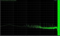
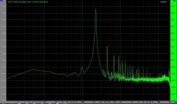
I have been trying a lot to reduce the even order harmonic distortion in the Signed Magnitude TDA1541A DAC, but not with great success. In order to minimize distortions from the I/V , I made an opamp I/V , just to measure, and here are the results:
First pic is the noise/spuriouses when there is no signal in.
Second is with full scale digital input.
Is this what can be expected?
Any comments? John?
Back again after 17 days on Bali
I have been trying a lot to reduce the even order harmonic distortion in the Signed Magnitude TDA1541A DAC, but not with great success. In order to minimize distortions from the I/V , I made an opamp I/V , just to measure, and here are the results:
First pic is the noise/spuriouses when there is no signal in.
Second is with full scale digital input.
Is this what can be expected?
Any comments? John?
Attachments
Those thd graphs aren't good or bad for a 30 years old dac, they are actually very good for any audio equipment...The biggest problem is aiming at too low thd! THD= total HARMONIC distortions , not total non-harmonic distortions!Don't you like harmony in your life?
Ohh yes !What I was asking for actually, was if this is a normal spectrum when you use TDA1541A in signed magnitude mode. It could be an error in the circuit I use and then cause other problems. So I wanted to know if it is representative of the signed magnitude mode.
When you use it in standard mode the THD is much much lower, even if it is a 30 + years old DAC chip!
When you use it in standard mode the THD is much much lower, even if it is a 30 + years old DAC chip!
Hi Kolby,
Do you have a THD graph of simultaneous mode to compare?
What I was asking for actually, was if this is a normal spectrum when you use TDA1541A in signed magnitude mode. It could be an error in the circuit I use and then cause other problems. So I wanted to know if it is representative of the signed magnitude mode.
When you use it in standard mode the THD is much much lower, even if it is a 30 + years old DAC chip!
It might be good enough, but it simply does not conform to the specs of -95 THD @ 0dB input signal or -42dB THD @-60dB input signal.
So it seems not o.k. from a technical point of view.
Hans
Excatly, but as you are using TWO TDA1541A, one in the positive half and one in the negative half, it is probably the small differences between the two TDA1541A that produces the even order distortion and probably unavoidable in this application, but I wondered if the figures I measure are excessive.It might be good enough, but it simply does not conform to the specs of -95 THD @ 0dB input signal or -42dB THD @-60dB input signal.
So it seems not o.k. from a technical point of view.
Hans
Sorry I do not have the graphs , but I know the 2. (and 3.) harmonic was about -90 dB.Hi Kolby,
Do you have a THD graph of simultaneous mode to compare?
Sorry I do not have the graphs , but I know the 2. (and 3.) harmonic was about -90 dB.
In normal (and simultanious mode) the 2. and 3. are almost the same @ FS.
In signed magnitude , even order is more prominent, and John even said that this should be expected, but he said it was a slight increase in even order distortion. My problem is, that I see it as substantially increase in even harmonic distortion. Whether this is a problem or even audibly, is another thing, but I just wanted to be sure nothing was wrong in the way the Signed Magnitude was implemented. I have documented the benefits (lacking spike in the zero crossing point) of the Signed Magnitude, so maybe this is just all fine...
Excatly, but as you are using TWO TDA1541A, one in the positive half and one in the negative half, it is probably the small differences between the two TDA1541A that produces the even order distortion and probably unavoidable in this application, but I wondered if the figures I measure are excessive.
So what’s the benefit of dividing the signal over two dac’s when the result means taking a big step back.
The least I would expect is an improvement of sqrt(2) or 3dB.
That’s what you get when having two dac’s in parallel.
So something must be wrong.
Hans
So what’s the benefit of dividing the signal over two dac’s when the result means taking a big step back.
The least I would expect is an improvement of sqrt(2) or 3dB.
That’s what you get when having two dac’s in parallel.
So something must be wrong.
Hans
The benefits, as explained by John, who came up with this idea and states this is the best way to implement the TDA1541A, is that you have no zero crossing spike.
When used in normal mode (simultanious or not two DACs in parallel or not) at zero crossing the registers changes from 1111111111111111 to 0000000000000000 and this produces a huge spike . This is dealt with when you use two TDA1541A and use the MSB to determine wich DAC gets the data (+ or -) so the zero crossing only changes 1 LSB (and in this case the 17th bit as it now actually is a 17 bit dac) .
The proof of this can be seen in post #7074.
This has nothing to do with paralleling two TDA1541A.
Yes I know all the technical backgrounds, I'm just saying something is not O.K.
As a technical challenge it's a nice experiment, splitting the signal in two halves.
What you could do is to offer a -90.31dBFS signal that only triggers the three lowest levels, resp 1, 0 and -1.
When you don't see these three levels, there is something wrong in going from one Dac to the other one.
See image below as an example.
Hans
Attachments
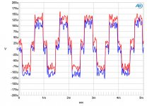
Attached: the second picture is a picture of a 5% full scale digital 300 Hz sinus from a TDA1541A running simultaneous mode with stopped clock.
The first is a closeup of that around the zero crossing. It is easy to see the big spike, when TDA1541A is changing all the bits at once. No spikes on any of the other transisions. Good reason to try Sign Magnitude
I've heard about this before and now i took the time to read your explanation, ecdesigns explanation too, but the photo with that spike convinced me for once that i can fully ignore this issue.The proof of this can be seen in post #7074.
Reason:
The spike has less than 1/10...1/20 of the energy than a whole step, its not even the same voltage magnitude as the upper step, so the integer circuit after it will simply swallow it.
More on this, at lower levels the i/v circuit noise itself can mask that spike entirely .Dithering in mastering audio(being it done by the sound engineer ) can make this problem even more irrelevant because they mix an entire musical program so that you can clearly hear only what's relevant and they think of it in advance, how to make a poor sounding audio system sound reasonably well.
There's not a single day where i won't hear problems that never really matter in the audio reproduction world.
I have three cheap tda1541 based cd players , one is fully functional , it doesn't even have a low pass filter in its stock form and it sounds very well.I don't think that there really is a problem if it doesn't meet the "no distortion in zero crossing area" criteria.I can't hear it because of the i/v stage noise...
Last edited:
- Home
- Source & Line
- Digital Line Level
- Building the ultimate NOS DAC using TDA1541A