Ok. It sounds like there is more than 1 view on how the TDA1541A could/should be configured with respect to DEM reclocking vs NOT reclocking. From your answer, it seems you are on the NOT reclocking side. So, are you using the SAA7220 chip in front of your DAC? Or is your TDA1541A in NOS mode?
Gary
I meant the TDA1541 will work fine insofar that you should get the datasheet promised level of performance without doing anything fancy with the DEM, so it should not be the source of your problems.
How I have implemented the TDA1541A can be seen in this thread: http://www.diyaudio.com/forums/digi...her-tda1541a-based-dac-dual-differential.html I do generate a synchronous DEM from BCLK.
Ok - understood.
However, I cannot imagine this issue being caused by the analog (FET) output stage...the search continues.
actually... I think the output stage is the prime suspect. Assuming your inputs to the TDA are fine (i2s, power), and the chip itself is not broken, the distortion should originate from the analog section (interference?)....
studiostevus;
With your reply (and thank you for this), we're now back to the original post: has anyone else implemented EC Designs Mk VII including the output stage?
According to Mr.Brown, it works well as it seems he has designed and built it, perhaps a few. I cannot think he would post something that does not work. I'm getting sinister results of 3% distortion on both channels, but do not see anything obvious.

Gary
Hi,
Thanks for taking the time to answer.
The DC offset has been nulled to 0V at the output. The output voltage is 2Vp. I've also tried a coupling cap, but no change. As indicated, the FFT on my Tek scope confirms the presence of harmonics. It's interesting to note that without any filters applied on my HP8903B (audio analyzer) the distortion is 4%. With a 80KHz LPF, it's about 3.2%. With a 30KHz LPF, it's down to 1.1%, indicating higher order harmonics - perhaps some odd non-linear mixing going on.
The PCB is my layout, but pretty much follows EC Designs MK VII schematic he posted here on this thread. I'm using good layout rules, the PCB was manufactured. Completely bypassed everywhere, local power filtering,etc. Using 1uF decoupling at underside directly to pins. For supply voltages, I'm using Salas shunt regulators. All pin voltages at nominal values. The input uses a Teralink (Teradak) X2 USB to I2S, and I'm getting perfect
non-distorted signals in at pins 1 & 2. (2.82MHz BCLK, 44.1KHz LE/Word CLK)
As I indicated, the only difference at this point is that I am using a 470pF at pins 16,17 instead of a DEM re-clocking scheme. (This is on a different PCB but not yet completed) I did scope at pins 16,17 and find the oscillator to be around 230KHz. However, I find it difficult to believe that using just this cap (in lieu of DEM reclocking) would cause the distortion to be that high. After all, most high end CD players used just this and got much lower distortion.
Has anyone else in the forum actually measured this circuit's distortion, or looked at the spectral content with an FFT? Otherwise, I must be losing me marbles because I do not see where the problem is.
Any suggestions or input on your experience would be appreciated. I was hoping to hear from Mr.Brown himself as his experience would be most beneficial, but any input is welcome!
Thanks,
Gary
I don't think you can use such a high bandwidth device like the HP8903B to measure THD of a NOS dac. Because with NOS even with the analog filtering you have a ton of aliasing.
Can you post a screen shot of 1khz FFT ? Ie how far down is the second harmonic?
It's interesting to note that without any filters applied on my HP8903B (audio analyzer) the distortion is 4%. With a 80KHz LPF, it's about 3.2%. With a 30KHz LPF, it's down to 1.1%, indicating higher order harmonics - perhaps some odd non-linear mixing going on.
Its a NOS DAC right? So those measurements show its not harmonic distortion you're seeing but aliasing. Because it decreases substantially between 80kHz and 30kHz its showing that most of the non-harmonic distortion is between those two frequencies - i.e. centred on 44k1. With aliasing on a NOS DAC, the 'THD' measurement will get close to 100% as you approach 20kHz test frequency. That's because the aliasing distortion is a reflection in the sampling frequency, 20kHz gives 24k1 aliasing component at a very high level.
I don't think you can use such a high bandwidth device like the HP8903B to measure THD of a NOS dac. Because with NOS even with the analog filtering you have a ton of aliasing.
Can you post a screen shot of 1khz FFT ? Ie how far down is the second harmonic?
Hi,
I've excluded the analog outout stage to eliminate that from the equation. The current output now flows through a 30 ohm resistor to ground. The peak voltage developed across the 30 ohm resistor is about 60mV peak, which seems right. (should be 1/2 FS current)
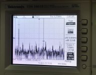
Attached is an FFT from the scope. It's as ugly as when it goes through the FET output stage. The bandwidth displayed of the FFT measurement is just 9KHz. You can see there's a lot of trash there. The first marker is at 1KHz, the second (just for somewhere to put it) is at 7.4KHz, a multiple of...what?
Hope this helps someone...give me some insight. What would be really nice is to see some measurements from someone who has made the same circuit, or perhaps had similar issues.
Lots of guesses...but still no smoking gun.
Gary
Attachments
Its a NOS DAC right? So those measurements show its not harmonic distortion you're seeing but aliasing. Because it decreases substantially between 80kHz and 30kHz its showing that most of the non-harmonic distortion is between those two frequencies - i.e. centred on 44k1. With aliasing on a NOS DAC, the 'THD' measurement will get close to 100% as you approach 20kHz test frequency. That's because the aliasing distortion is a reflection in the sampling frequency, 20kHz gives 24k1 aliasing component at a very high level.
Hi,
Thanks for the information. OK. let's forget the 8903B for now, and just look at the FFT from my Tek scope.
The FFT I just posted paints a nasty looking picture with all kinds of harmonics in band - and that's just from 1KHz to 9KHz.
So forgetting that there's aliasing information above 1/2fs (22KHz), what does your explanation say for the in band signal?
I guess I do not understand what's going on: I've seen a gaZIllion posts from NOS DACs, with beautiful FFT's showing a nice first harmonic, and a second down at -80, etc, etc.
I think clearly there's an issue with mine...what do you think?
Gary
I don't think you can use such a high bandwidth device like the HP8903B to measure THD of a NOS dac. Because with NOS even with the analog filtering you have a ton of aliasing.
Can you post a screen shot of 1khz FFT ? Ie how far down is the second harmonic?
Hi regal,
Thanks for the reply. I've posted a couple of updates...the FFT tells the story.
Gary
Hi,
Thanks for the information. OK. let's forget the 8903B for now, and just look at the FFT from my Tek scope.
Yeah I looked - good job that Tek are kind enough to show the acquisition sample rate on the screen isn't it? Look - it says '25kS/sec'. Does that help you understand what you're seeing? In short - you're probably seeing aliasing caused by the scope. But I haven't done the sums - you can have a go at the math to see if my hypothesis makes sense
I think clearly there's an issue with mine...what do you think?
FWIW I think you should clean your window before saying the dirt's in the garden
Last edited:
Yeah I looked - good job that Tek are kind enough to show the acquisition sample rate on the screen isn't it? Look - it says '25ks/sec'. Does that help you understand what you're seeing? In short - you're probably seeing aliasing caused by the scope. But I haven't done the sums - you can have a go at the math to see if my hypothesis makes sense
FWIW I think you should clean your window before saying the dirt's in the garden
Nice pie, thanks!

Roger, if you are measuring at the DACi-out across an I/v resistor you are just measuring squarewaves.
Suggestion, hook up the analog stage and take a FFT with a soundcard (44.1 in 44.1 out). Those NOS DAC measurements you are comparing yours to are from a soundcard ADC, where there is an input filter and oversampling!
Measuring an NOS DAC, you sort of have to throw away textbook EE thinking and remember that the whole princible involves your ears filtering out the aliasing.
Hi all
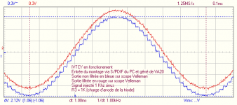
This picture is about TDA1543 in NOS mode with our IVTCY (I/V with tube )
the blue line is 1 Khz generated with the 44.1 Khz juxtaposed
count the number of stairs
the red line use a notch filtre around 44.1 Khz
Hope it help
This picture is about TDA1543 in NOS mode with our IVTCY (I/V with tube )
the blue line is 1 Khz generated with the 44.1 Khz juxtaposed
count the number of stairs
the red line use a notch filtre around 44.1 Khz
Hope it help
Attachments
Last edited:
Using 44k1 might just confuse.
Sorry but i don't use 44.1 Khz , the chip (TDA1543 here) produce it
the pure 1Khz is generated by different source of software
use different kind of output (CD , USB by PCM2904 with different sofware )
All the time the same curve with stairs coming from the output of the TDA
I think it's a result of conversion in the chip
the reason of analog filter in the output in many DAC
Hi roger57,
Over the past years I mainly relied on listening impressions of highly critical audiophiles in order to get realistic feedback. If the distortion was 3% I would have gotten remarks for sure.
High distortion could be caused by exceeding TDA1541A output compliance, low pass filter, or by the load connected to the 500 Ohm passive I/V resistor (MK7 output is not buffered).
According to Mr.Brown, it works well as it seems he has designed and built it, perhaps a few. I cannot think he would post something that does not work. I'm getting sinister results of 3% distortion on both channels, but do not see anything obvious.
Over the past years I mainly relied on listening impressions of highly critical audiophiles in order to get realistic feedback. If the distortion was 3% I would have gotten remarks for sure.
High distortion could be caused by exceeding TDA1541A output compliance, low pass filter, or by the load connected to the 500 Ohm passive I/V resistor (MK7 output is not buffered).
Hi roger57,
The THD measurements of NOS DACs are ugly, but then, the brickwall filtering of the human auditory system is not included in this measurement.
With OS DACs there is double brickwall filtering, first at the DAC, then at the human auditory system.
The digital brickwall filter is required because the connected equipment was designed for processing audio frequency spectrum only. This changes when using equipment specially designed to handle large bandwidth signals.
Most speakers can handle large bandwidth signals, but capacitors and chokes may cause some minor problems. The speaker chassis have mechanical limitations, frequencies exceeding say 25 KHz are converted into heat.
One of the errors caused by every digital brickwall filter is the fact that the sample rate needs to be increased (oversampling). This reduces the sample pulse width by factor 4 ... 32.
With given timing fluctuations (jitter) in the system, the impact of these timing fluctuations increases as sample pulse width decreases (errors are amplified by the OS factor). Similar, rounding errors occur due to finite digital filter precision, the higher the precision, the lower the rounding errors. Other problem is the noise and related jitter generated by the digital filter logic circuits, this noise cannot be fully blocked, especially when the digital filter is integrated with the highly sensitive DAC circuit.
Hi,
I've excluded the analog outout stage to eliminate that from the equation. The current output now flows through a 30 ohm resistor to ground. The peak voltage developed across the 30 ohm resistor is about 60mV peak, which seems right. (should be 1/2 FS current)
Attached is an FFT from the scope. It's as ugly as when it goes through the FET output stage. The bandwidth displayed of the FFT measurement is just 9KHz. You can see there's a lot of trash there. The first marker is at 1KHz, the second (just for somewhere to put it) is at 7.4KHz, a multiple of...what?
Hope this helps someone...give me some insight. What would be really nice is to see some measurements from someone who has made the same circuit, or perhaps had similar issues.
Lots of guesses...but still no smoking gun.
The THD measurements of NOS DACs are ugly, but then, the brickwall filtering of the human auditory system is not included in this measurement.
With OS DACs there is double brickwall filtering, first at the DAC, then at the human auditory system.
The digital brickwall filter is required because the connected equipment was designed for processing audio frequency spectrum only. This changes when using equipment specially designed to handle large bandwidth signals.
Most speakers can handle large bandwidth signals, but capacitors and chokes may cause some minor problems. The speaker chassis have mechanical limitations, frequencies exceeding say 25 KHz are converted into heat.
One of the errors caused by every digital brickwall filter is the fact that the sample rate needs to be increased (oversampling). This reduces the sample pulse width by factor 4 ... 32.
With given timing fluctuations (jitter) in the system, the impact of these timing fluctuations increases as sample pulse width decreases (errors are amplified by the OS factor). Similar, rounding errors occur due to finite digital filter precision, the higher the precision, the lower the rounding errors. Other problem is the noise and related jitter generated by the digital filter logic circuits, this noise cannot be fully blocked, especially when the digital filter is integrated with the highly sensitive DAC circuit.
I thought i'd post the results of my recent efforts. I have implemented the mk7 clock and reclocker circuit, and used a squeezebox (synch) as source. The output stage is pedja rogic's diamond stage.
My psu is based on oversized capacitors (135000 uf.. Maybe not really necessary) followed by Salas shunt regs for -15, -5, +5 (tda), +5 (reclocker) voltages. At the moment they are offboard, but in the final versions i will put the regs on the same pcb as the dac. Has anyone compared the salas shunts to the discrete regs posted in this thread? John maybe?
Dirty prototype...
My psu is based on oversized capacitors (135000 uf.. Maybe not really necessary) followed by Salas shunt regs for -15, -5, +5 (tda), +5 (reclocker) voltages. At the moment they are offboard, but in the final versions i will put the regs on the same pcb as the dac. Has anyone compared the salas shunts to the discrete regs posted in this thread? John maybe?
An externally hosted image should be here but it was not working when we last tested it.
Dirty prototype...
- Home
- Source & Line
- Digital Line Level
- Building the ultimate NOS DAC using TDA1541A