Is "dynamic tracking" a measurable parameter? If it is (in contrast to transparency and naturalness, which are the resulting subjective parameters), how do you measure 1ns and 1nV tracking error? I am very interested in measuring methods in general, and in particular in the correlation between measurable and subjective parameters.
Dynamic tracking isn't a single parameter, it shows how well a circuit can handle complex signals like music for example.
It can theoretically be measured by logging both input and output signals in real-time with sufficient time and amplitude resolution to capture all audible flaws. The circuit is fed by at least 100 carefully selected audio test tracks with approx. 10 minutes duration. So measuring time equals at least 16 hours. Analysis of the logged data could take much longer, depending on algorithm and amount of logged data.
The logged data then passes an algorithm that translates measured data into a rating that represents the level of circuit tracking accuracy. However, different errors can result in similar tracking property rating. In order to offer more precise analysis, a list of properties similar to description of perceived sound quality could be generated. So there could be a derived rating for circuit transparency, dynamics, resolution, refinement and so on.
The problem is that there are no suitable measuring instruments nor computer systems available today to perform required measurements and analysis.
So for now it seems we have to rely on listening tests.
the great complex signal myth
It gernerally comes into play when people run out of arguments.
If someone mentiones complex signal, you're chess mate.
I suggest looking at a square, small & large signal, measure slew rate, overshoot, settling time.
That gives you a picture.
It gernerally comes into play when people run out of arguments.
If someone mentiones complex signal, you're chess mate.
I suggest looking at a square, small & large signal, measure slew rate, overshoot, settling time.
That gives you a picture.
Hi,
Is that the one that runs on WebOs and the HP Touch Me, Touch me, Touch Me (Sam Fox) TouchPad?
Ciao T
or wait for the hp audio transparency analyzer
Is that the one that runs on WebOs and the HP Touch Me, Touch me, Touch Me (Sam Fox) TouchPad?
Ciao T
Hi Bernhard,
I perform basic measurements like the one's you mentioned plus some other like tests with multiple non-synchronized sine waves of different amplitude, triangle waves, sawtooth waves, burst signals and measurements with audio tracks to check circuit basic functionality. But these tests won't show all circuit flaws that are still clearly audible and often very annoying. That's the basic problem with measurements.
It seems to be a problem with both, measuring equipment resolution and measurement method.
It gernerally comes into play when people run out of arguments.
If someone mentiones complex signal, you're chess mate.
I suggest looking at a square, small & large signal, measure slew rate, overshoot, settling time.
That gives you a picture.
I perform basic measurements like the one's you mentioned plus some other like tests with multiple non-synchronized sine waves of different amplitude, triangle waves, sawtooth waves, burst signals and measurements with audio tracks to check circuit basic functionality. But these tests won't show all circuit flaws that are still clearly audible and often very annoying. That's the basic problem with measurements.
It seems to be a problem with both, measuring equipment resolution and measurement method.
EC what about a basic frequency sweep with a 10k load? I am still not convinved that the +5V ground is a good idea, output impedance from the +5V supply will certainly give a skew to freq/phase plot.
Its ideal for using a 1:1 output transformer since there will be no DC offset, however that is the only means I can think of to use this mk7 analog stage as part of a standalone DAC. Certainly the following amplifier or preamp wouldn't work without some sort of galvanic isolation.
Its ideal for using a 1:1 output transformer since there will be no DC offset, however that is the only means I can think of to use this mk7 analog stage as part of a standalone DAC. Certainly the following amplifier or preamp wouldn't work without some sort of galvanic isolation.
Last edited:
Hi,
It is important to realise that there is no such thing as "ground". It is a fiction, a concept to make understanding things easier, that's all.
In principle anything can be "ground" as long as we call it "ground".
In many circuits it is in fact the power supply rail that is the ACTUAL "reference", against which the output voltage is developed. So it is incidentally with ECD's DAC....
Ciao T
EC what about a basic frequency sweep with a 10k load? I am still not convinved that the +5V ground is a good idea,
It is important to realise that there is no such thing as "ground". It is a fiction, a concept to make understanding things easier, that's all.
In principle anything can be "ground" as long as we call it "ground".
In many circuits it is in fact the power supply rail that is the ACTUAL "reference", against which the output voltage is developed. So it is incidentally with ECD's DAC....
Ciao T
Hi,
It is important to realise that there is no such thing as "ground". It is a fiction, a concept to make understanding things easier, that's all.
In principle anything can be "ground" as long as we call it "ground".
In many circuits it is in fact the power supply rail that is the ACTUAL "reference", against which the output voltage is developed. So it is incidentally with ECD's DAC....
Ciao T
No kidding, but a +5V PS lifted ground will have an output impedance.
Also, Tell that to my amp when its ground reference is +5V on the signal input and 0VDc tied to earth on everything else. Don't think that would go over well.
Last edited:
Hi,
Impedance with respect to WHAT?
If we designate the +5V line as signal reference it IS the reference.
The two I/V conversion resistors are referenced to this +5V line, so using the +5V line as reference means the output signal loop is closed directly, rather than through the 5V supply, which would be the case if we used "ground" as reference.
Yes, but why would you tie the local "0V" to earth?
Anyway, short and sweet, there is no problem if all this done right.
To understand better forget you ever heard of "ground" and just blook where current flows...
Ciao T
No kidding, but a +5V PS lifted ground will have an output impedance.
Impedance with respect to WHAT?
If we designate the +5V line as signal reference it IS the reference.
The two I/V conversion resistors are referenced to this +5V line, so using the +5V line as reference means the output signal loop is closed directly, rather than through the 5V supply, which would be the case if we used "ground" as reference.
Also, Tell that to my amp when its ground reference is +5V on the signal input and 0VDc tied to earth on everything else. Don't think that would go over well.
Yes, but why would you tie the local "0V" to earth?
Anyway, short and sweet, there is no problem if all this done right.
To understand better forget you ever heard of "ground" and just blook where current flows...
Ciao T
John, couple of questions on your clock design. I measured the signals on the scope. Here are the pics:
this is after the diode and resistor. You see the rise time is shorter, but it lost its sine shape.
This is after the coil, before the diode. It has ugly bottom shape...
This is at the crystal... Looks fine.
1. Is the signal supposed to behave this way?
2. What causes the skewing? Coil Q?
3. Are there harmful effects on jitter?
Thank!
this is after the diode and resistor. You see the rise time is shorter, but it lost its sine shape.
An externally hosted image should be here but it was not working when we last tested it.
This is after the coil, before the diode. It has ugly bottom shape...
An externally hosted image should be here but it was not working when we last tested it.
This is at the crystal... Looks fine.
An externally hosted image should be here but it was not working when we last tested it.
1. Is the signal supposed to behave this way?
2. What causes the skewing? Coil Q?
3. Are there harmful effects on jitter?
Thank!
The two I/V conversion resistors are referenced to this +5V line, so using the +5V line as reference means the output signal loop is closed directly, rather than through the 5V supply, which would be the case if we used "ground" as reference.
Ciao T
Offtopic (yet?): my local electronics store took over a huge ammount of components from a closing bigger store and moved all to the south. I browsed through the components and found the tda154x section. Nearly empty; a lonely 1540 and some 1543(A)s. And a few 1542s, which i remember to be a philips filter chip. So i brought one home to play and dug up the datasheet.
Turns out to be just a collection of opamps (including headphone out). Supply is +12 and -12 for all the opamps, only the first one (i/v) is +5 and -12, it has a separate positive supply. Maybe philips was not as stupid as we think
 I hope it is for te same reason and the first opamp is developed with the returnpath in mind.
Planning to do some further trials with it. It was not used a lot, cd207 and a video cd player is al i could find. Strange is that mine is from '94, they were made for years, but not used in the players philips/marantz build. Not good enough, too expensive, don't know.
Hi,
Impedance with respect to WHAT?
If we designate the +5V line as signal reference it IS the reference.
The two I/V conversion resistors are referenced to this +5V line, so using the +5V line as reference means the output signal loop is closed directly, rather than through the 5V supply, which would be the case if we used "ground" as reference.
Yes, but why would you tie the local "0V" to earth?
Anyway, short and sweet, there is no problem if all this done right.
To understand better forget you ever heard of "ground" and just blook where current flows...
Ciao T
I understand fully. Without galvanic isolation between this output stage and an amp or preamp the 5v+ supply will see a dead short.
All I am saying is this is not a stand alone DAC without a line transformer or cap, unless the preamp or amp is integrated.
Hi,
No, it will not. Clearly you do NOT understand.
As it has no SPDIF Input it is not a standalone DAC. It is part of a solution that includes an SD Card transport. There is no connection to earth in this.
Now if you are building something else, then you are building something else...
CiaoNT
I understand fully. Without galvanic isolation between this output stage and an amp or preamp the 5v+ supply will see a dead short.
No, it will not. Clearly you do NOT understand.
All I am saying is this is not a stand alone DAC without a line transformer or cap, unless the preamp or amp is integrated.
As it has no SPDIF Input it is not a standalone DAC. It is part of a solution that includes an SD Card transport. There is no connection to earth in this.
Now if you are building something else, then you are building something else...
CiaoNT
Hi,
......
.
Now if you are building something else, then you are building something else...
CiaoNT
new logic?
Hi,
No, old logic.
If I show you how to make a wheel, with the hole in center and round on the outside and you make one like I showed you, then we have both have made the same.
If you insist that the hole needs to be off center and outside contour not circular but instead an ellipse, clearly you are not making a wheel. So in this case any debate how inapproriate the shape of my wheel is pointless, as for my purose the wheel is excellent and has an appropriate shape.
Ciao T
new logic?
No, old logic.
If I show you how to make a wheel, with the hole in center and round on the outside and you make one like I showed you, then we have both have made the same.
If you insist that the hole needs to be off center and outside contour not circular but instead an ellipse, clearly you are not making a wheel. So in this case any debate how inapproriate the shape of my wheel is pointless, as for my purose the wheel is excellent and has an appropriate shape.
Ciao T
Last edited:
Hi regal,
I also used frequency sweeps / phase measurement. I programmed my frequency generator to sweep from approx. 10 Hz to 100 Khz while using oscilloscope x and y inputs creating a lissajous pattern. If phase is correct, a thin line with approx. 45 degree angle is displayed on the scope screen. If the line turns into a loop shape, both input and output are not exactly in phase. This measurement can also be carried out with music instead of a sweep.
This is fine to check circuit phase accuracy, but still tells very little about how the circuit will handle multiple fundamentals plus harmonics of different varying amplitude being processed simultaneously.
The other problem is that I use large bandwidth signal processing, DC ... MHz range. The MK7 NOS DAC step output signal is maintained (unfiltered) up to the speakers. So the signal on the speaker terminals looks virtually identical to the MK7 output, it just has different amplitude.
This minimizes the errors added to the sample pulses (pulse width / pulse amplitude). Filtering directly after the DAC will change pulse shape / energy leading to increased trebles roll-off, phase distortion, non-linearities and dynamic tracking errors.
The speakers have filters that also add errors, but these are at the end of the signal path and their effects are not amplified. The signals are also largest here and have highest energy level (watts) so are least sensitive to interference.
This large bandwidth processing also improves perceived sound quality from other sources like tape recorder and record player. I suspect large bandwidth signal processing offers higher time resolution, similar to an oscilloscope for example that has larger bandwidth.
For clarity, The MK7 output signal is taken directly from the "hot" side of the 500 Ohm passive I/V resistor that has +4V potential, and a clean passive, adjustable 4V DC reference voltage. So the net DC offset at the RCA socket equals 0V.
The voltage developed across the 500 Ohm passive I/V resistor runs through the connected shunt volume regulator, back to the +4V reference, back to +5V. The +4V DC reference voltage is decoupled to +5V instead of GND.
If I would use the conventional GND (0V) I would place the +5V power supply plus its noise and its non-linear impedance in series with the signal. So it is just the other way around, the conventional GND reference would cause most problems here.
I performed extensive tests with 1:1 coupling transformers and TVC. I failed to get similar performance of a DC-coupling that served as reference. Logically speaking, full DC-coupling is -required- if one strives for optimal transparency. Every coupling cap or coupling transformer will color / distort the sound to some degree, failing to achieve optimal transparency.
Coupling caps have problems passing low level signals, add distortion due to both, mechanical and electrical resonances. They also introduce low frequency roll-off, introducing phase errors at the low end. If you have to use them, put them at the end of the signal path (speaker crossover filter) and use the best possible caps you can get. I tested many different coupling / filter caps. The only ones that I am satisfied with (for speaker crossover only) are V-cap TFTF and Duelund VSF copper foil. I didn't test Duelund cast copper paper in oil yet.
Note that I always use a suitable bypass resistor for the coupling / filter caps, these greatly optimize low level performance. The resistor value depends on application and tolerated DC leakage current. I use 8.2 K Ohm bypass resistors on the Duelund VSF copper foil filter caps in my speaker crossover filters.
Here is a link for capacitor comparison:
Humble Homemade Hifi
Coupling transformers have problems with both low frequencies and large signal amplitude. There is also high frequency roll-off due to stray capacitance. So transformer bandwidth is limited at both, low and high frequencies. This introduces phase errors within the audio range. Coupling transformers can also cause spurious (RF) oscillations when not properly loaded. If you have to use chokes in a passive speaker crossover, use a winding method that introduces lowest possible stray capacitance, litz wire, and always use an air core.
With DC-coupling I can easily obtain a bandwidth from DC up to a few hundred MHz, this in turn minimizes phase errors within the audio range.
output impedance from the +5V supply will certainly give a skew to freq/phase plot.
I also used frequency sweeps / phase measurement. I programmed my frequency generator to sweep from approx. 10 Hz to 100 Khz while using oscilloscope x and y inputs creating a lissajous pattern. If phase is correct, a thin line with approx. 45 degree angle is displayed on the scope screen. If the line turns into a loop shape, both input and output are not exactly in phase. This measurement can also be carried out with music instead of a sweep.
This is fine to check circuit phase accuracy, but still tells very little about how the circuit will handle multiple fundamentals plus harmonics of different varying amplitude being processed simultaneously.
The other problem is that I use large bandwidth signal processing, DC ... MHz range. The MK7 NOS DAC step output signal is maintained (unfiltered) up to the speakers. So the signal on the speaker terminals looks virtually identical to the MK7 output, it just has different amplitude.
This minimizes the errors added to the sample pulses (pulse width / pulse amplitude). Filtering directly after the DAC will change pulse shape / energy leading to increased trebles roll-off, phase distortion, non-linearities and dynamic tracking errors.
The speakers have filters that also add errors, but these are at the end of the signal path and their effects are not amplified. The signals are also largest here and have highest energy level (watts) so are least sensitive to interference.
This large bandwidth processing also improves perceived sound quality from other sources like tape recorder and record player. I suspect large bandwidth signal processing offers higher time resolution, similar to an oscilloscope for example that has larger bandwidth.
I am still not convinced that the +5V ground is a good idea
For clarity, The MK7 output signal is taken directly from the "hot" side of the 500 Ohm passive I/V resistor that has +4V potential, and a clean passive, adjustable 4V DC reference voltage. So the net DC offset at the RCA socket equals 0V.
The voltage developed across the 500 Ohm passive I/V resistor runs through the connected shunt volume regulator, back to the +4V reference, back to +5V. The +4V DC reference voltage is decoupled to +5V instead of GND.
If I would use the conventional GND (0V) I would place the +5V power supply plus its noise and its non-linear impedance in series with the signal. So it is just the other way around, the conventional GND reference would cause most problems here.
Its ideal for using a 1:1 output transformer since there will be no DC offset, however that is the only means I can think of to use this mk7 analog stage as part of a standalone DAC. Certainly the following amplifier or preamp wouldn't work without some sort of galvanic isolation.
I performed extensive tests with 1:1 coupling transformers and TVC. I failed to get similar performance of a DC-coupling that served as reference. Logically speaking, full DC-coupling is -required- if one strives for optimal transparency. Every coupling cap or coupling transformer will color / distort the sound to some degree, failing to achieve optimal transparency.
Coupling caps have problems passing low level signals, add distortion due to both, mechanical and electrical resonances. They also introduce low frequency roll-off, introducing phase errors at the low end. If you have to use them, put them at the end of the signal path (speaker crossover filter) and use the best possible caps you can get. I tested many different coupling / filter caps. The only ones that I am satisfied with (for speaker crossover only) are V-cap TFTF and Duelund VSF copper foil. I didn't test Duelund cast copper paper in oil yet.
Note that I always use a suitable bypass resistor for the coupling / filter caps, these greatly optimize low level performance. The resistor value depends on application and tolerated DC leakage current. I use 8.2 K Ohm bypass resistors on the Duelund VSF copper foil filter caps in my speaker crossover filters.
Here is a link for capacitor comparison:
Humble Homemade Hifi
Coupling transformers have problems with both low frequencies and large signal amplitude. There is also high frequency roll-off due to stray capacitance. So transformer bandwidth is limited at both, low and high frequencies. This introduces phase errors within the audio range. Coupling transformers can also cause spurious (RF) oscillations when not properly loaded. If you have to use chokes in a passive speaker crossover, use a winding method that introduces lowest possible stray capacitance, litz wire, and always use an air core.
With DC-coupling I can easily obtain a bandwidth from DC up to a few hundred MHz, this in turn minimizes phase errors within the audio range.
Last edited:
Hi regal,
I don't have galvanic insulation between SD-player, stepped shunt volume control and Circlotron monoblocks. +5V SD-player supply is not shorted as it works fine.
In order to short the +5V I need to feed both, +5V and GND (0V) to the connected equipment.
GND (0V) is not connected to any external circuits, +5V is not connected to any external circuits.
I use the hot side of the 500R passive I/V resistor (500 Ohms to +5V) and a passive 4V reference voltage (approx. 200 Ohms to +5V) only.
I understand fully. Without galvanic isolation between this output stage and an amp or preamp the 5v+ supply will see a dead short.
I don't have galvanic insulation between SD-player, stepped shunt volume control and Circlotron monoblocks. +5V SD-player supply is not shorted as it works fine.
In order to short the +5V I need to feed both, +5V and GND (0V) to the connected equipment.
GND (0V) is not connected to any external circuits, +5V is not connected to any external circuits.
I use the hot side of the 500R passive I/V resistor (500 Ohms to +5V) and a passive 4V reference voltage (approx. 200 Ohms to +5V) only.
Hi studiostevus,
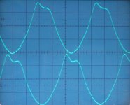
I attached oscillograms of the balanced output signal of the MK7 masterclock. The signal on the crystals should be a clean sine wave like you measured, the signal on the lateral MOSFET buffers should look like on the first oscillogram.
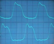
After the RF Schottky rectifiers, loaded with 330 Ohm it should look like in the second oscillogram.
The connected D flip-flop has low threshold voltage (it runs on approx. 2.4V power supply) and is triggered on the rising (steepest) edge of the rectified output signal. Power supplies for both masterclock and D flip-flops are extremely clean in order to minimize circuit trigger uncertainty.
John, couple of questions on your clock design. I measured the signals on the scope. Here are the pics:
this is after the diode and resistor. You see the rise time is shorter, but it lost its sine shape.
I attached oscillograms of the balanced output signal of the MK7 masterclock. The signal on the crystals should be a clean sine wave like you measured, the signal on the lateral MOSFET buffers should look like on the first oscillogram.
After the RF Schottky rectifiers, loaded with 330 Ohm it should look like in the second oscillogram.
The connected D flip-flop has low threshold voltage (it runs on approx. 2.4V power supply) and is triggered on the rising (steepest) edge of the rectified output signal. Power supplies for both masterclock and D flip-flops are extremely clean in order to minimize circuit trigger uncertainty.
Attachments
- Home
- Source & Line
- Digital Line Level
- Building the ultimate NOS DAC using TDA1541A