Did anyone implement the high voltage version of this output stage discussed a while ago? I am intrigued as to how it would perform into a pass F4 or a 2a3/PX4. Also, are the problems with using a switched IV resistor attenuator in this situation insurmountable?
I'm intrigued...
I'm intrigued...

Hi galeb,
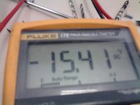
It's within specified voltage range of -14 ... -16V (Philips datasheet page 6). Absolute maximum voltage equals -17V (Philips datasheet page 5).
Hi, this is my TDA1541A -15vdc measurement, it equals -15.41V
It's within specified voltage range of -14 ... -16V (Philips datasheet page 6). Absolute maximum voltage equals -17V (Philips datasheet page 5).
As far as i know, there are no changes in sound quality by varying supply voltages (like in the 1543). I also use voltages slightly above 5 and 15v.
How have you guys arranged decoupling of these supplies? I am using:
-15v decoupling to -5v line (using 33uf black gate)
-5v decoupling to agnd (33uf bg)
+5v decoupling to dgnd (33uf bg)
Agnd and dgnd meet at pin 5 of the tda
How have you guys arranged decoupling of these supplies? I am using:
-15v decoupling to -5v line (using 33uf black gate)
-5v decoupling to agnd (33uf bg)
+5v decoupling to dgnd (33uf bg)
Agnd and dgnd meet at pin 5 of the tda
Hi maravedis,
I compared grounded grid buffer vs lateral MOSFET in the MK7 and I am still using the lateral MOSFET buffer.
Tubes add a lot of "things" like: coloration, distortion, noise and microphonics that are not optimal for a circuit that should offer highest possible transparency.
Here is an example of plain valve base vs gel valve base:
Audio Vibration Isolation, part 9, Absorb-GEL dampers
I also had a lot of problems with microphonics when experimenting with tubes. It is almost impossible to eliminate feedback between speakers and the mechanical construction inside the tube when both are placed in the same room. Since there is electrical charge between metal parts inside the tube, the slightest mechanical movement or resonance translates to voltage fluctuations causing distortion.
Things get worse as volume setting is turned up. Possible solution is placing the tube circuit in a different room.
Tubes also require coupling caps and / or coupling (output) transformers. Highest transparency requires fully DC-coupled signal path.
The required HV supply also prevents all TDA1541A bit currents flowing back into the +5V supply.
Did anyone implement the high voltage version of this output stage discussed a while ago? I am intrigued as to how it would perform into a pass F4 or a 2a3/PX4. Also, are the problems with using a switched IV resistor attenuator in this situation insurmountable?
I compared grounded grid buffer vs lateral MOSFET in the MK7 and I am still using the lateral MOSFET buffer.
Tubes add a lot of "things" like: coloration, distortion, noise and microphonics that are not optimal for a circuit that should offer highest possible transparency.
Here is an example of plain valve base vs gel valve base:
Audio Vibration Isolation, part 9, Absorb-GEL dampers
I also had a lot of problems with microphonics when experimenting with tubes. It is almost impossible to eliminate feedback between speakers and the mechanical construction inside the tube when both are placed in the same room. Since there is electrical charge between metal parts inside the tube, the slightest mechanical movement or resonance translates to voltage fluctuations causing distortion.
Things get worse as volume setting is turned up. Possible solution is placing the tube circuit in a different room.
Tubes also require coupling caps and / or coupling (output) transformers. Highest transparency requires fully DC-coupled signal path.
The required HV supply also prevents all TDA1541A bit currents flowing back into the +5V supply.
Hi John,
I know about the voltages range, just funny the measurement of -15v.
About the tube outputs, I'm currently using an aikido configuration, with 6N2P+6H23. At this moment I'm trying to avoid the output cap, but for now, I use a Vcap oil of 4,7uf. The supply is choke filtered with no polarity caps, a total of 282uf (47ufx6, clarity caps, ESA series). It sounds incredible well. No distorsion, superb and cristal clear highs, very sweet voices, and a noise level so low, that it can be heared the original master recording noise floor. The image is incredible big, with a lot of 3D stages. The bass is very well defined and the dynamic is fast as the speed of light. Once feeded the TDA voltages with a simple regulator with common mode ripple atenuators, the naturality of all is simply astounding, and feeding with the same regulation the reclock and the clock, wow, I don't have words to say what I feel. And last, the output voltage is 2V rms, wich is what I need.
Kind regards for all.
I2S modulation on L channel
I measured the residual output of a TDA1541A in circuit, by removing the analog low-pass section and amplifying the AC voltage by 100. At digital zero the R channel is pretty quiet , but the L channel has 10mV squarewave output at the WS rate (176.4kHz). That is about 1LSB! 1LSB = 4mA * 1.5k / 65536 = 91.6uV, if my calculation is correct.
Next I will try the I2S attenuator, but I just don't understand why only the L channel has this modulation? Could it be because of the PCB layout? I use a Philips CD820 PCB as testbed.
I compared grounded grid buffer vs lateral MOSFET in the MK7 and I am still using the lateral MOSFET buffer.
Tubes add a lot of "things" like: coloration, distortion, noise and microphonics that are not optimal for a circuit that should offer highest possible transparency.
Hi all
have you take a look at this http://www.diyaudio.com/forums/digital-line-level/188708-super-common-gate-valve-i-v-converter-tda1543.html
Hi oshifis,
The left channel (pin 25) crosses the I2S interface traces (wire bridge) and picks-up EMI (including 176.4 Khz) from the I2S interface.
I suggest to remove the complete L channel trace plus wire link from the PCB and reroute it properly using a piece of screened wire (screen connects to pin 5). This should fix the problem.
but I just don't understand why only the L channel has this modulation? Could it be because of the PCB layout? I use a Philips CD820 PCB as testbed.
The left channel (pin 25) crosses the I2S interface traces (wire bridge) and picks-up EMI (including 176.4 Khz) from the I2S interface.
I suggest to remove the complete L channel trace plus wire link from the PCB and reroute it properly using a piece of screened wire (screen connects to pin 5). This should fix the problem.
Hi all
have you take a look at this http://www.diyaudio.com/forums/digital-line-level/188708-super-common-gate-valve-i-v-converter-tda1543.html
You just can't dump a 1541 output into a 3V gate, even if it is near zero impedance, the TDA specs a max 25mv above its ground at its output.
I love your idea but I think it would require a negative supply and a servoed jfet ccs to work with the TDA1541 properly.
But With the NK7 single mofset output what sort of THD is being meaured? Not meaning to cause controversy, just curious with some ccda tda1541 tube stages meauring -90db 2h I'm struggling with thinking the single mofset would come anywhere close.
Last edited:
Perhaps SY's "Heretical III" buffer cct (or the Cavalli buffer) could be adapted with higher gain tubes, etc - they both maintain 0volts on the cathode with good servo's - not sure about impedance loads, etc ...
Along the same thoughts, Regal - does look quite interesting.
Along the same thoughts, Regal - does look quite interesting.
Perhaps SY's "Heretical III" buffer cct (or the Cavalli buffer) could be adapted with higher gain tubes, etc - they both maintain 0volts on the cathode with good servo's - not sure about impedance loads, etc ...
Along the same thoughts, Regal - does look quite interesting.
The low transconductance of tubes makes them a little less than ideally suited for common grid I/V. Take an ecc88 as used in the heretical for instance you can only get about ~10mS or so from it translating to an AC impedance of 100ohm at the TDA.
Taking a fet like the IRF610 (as in the D1) you get about ten times as much transconductance and hence only a tenth of the impedance as seen from the dac. (for practical operating points)
Also you must ensure the dac does not get killed by nasty voltages at the tubes cathode while the tube heats up.
Perhaps you could use something with higher transconductance (read a bjt) as a current conveyor from the output of the dac into the tube.
Perhaps you could use something with higher transconductance (read a bjt) as a current conveyor from the output of the dac into the tube.
That is something I have always wanted to try, common base BJT with CCS to keep the base at 0V, then tube gain stage. Basically a silicon version of audionotes I/V transformers (which I haven't had much liuck with.) I'm thinking THD should be etter than a single mofset.
Hi maravedis,
I compared grounded grid buffer vs lateral MOSFET in the MK7 and I am still using the lateral MOSFET buffer.
Tubes add a lot of "things" like: coloration, distortion, noise and microphonics that are not optimal for a circuit that should offer highest possible transparency.
Here is an example of plain valve base vs gel valve base:
Audio Vibration Isolation, part 9, Absorb-GEL dampers
I also had a lot of problems with microphonics when experimenting with tubes. It is almost impossible to eliminate feedback between speakers and the mechanical construction inside the tube when both are placed in the same room. Since there is electrical charge between metal parts inside the tube, the slightest mechanical movement or resonance translates to voltage fluctuations causing distortion.
Things get worse as volume setting is turned up. Possible solution is placing the tube circuit in a different room.
Tubes also require coupling caps and / or coupling (output) transformers. Highest transparency requires fully DC-coupled signal path.
The required HV supply also prevents all TDA1541A bit currents flowing back into the +5V supply.
Dear EC,
Actually I meant something different (although your answer is already very interesting!)
I was asking about a version of the MOSFET IV that would be able to drive a 2a3 directly. i.e. 40v p-p. It seems that this would be an ultra-simple signal path and I'd be interested if anyone had tried it and had success with this...
With the 1541 you only have 4mA P-P to play with so while theoretically you could get the voltage swing you need with a high enough I/V resistor and Bias voltage you'll still have to increase the current drive capability of the driver stage.
You just can't dump a 1541 output into a 3V gate, even if it is near zero impedance, the TDA specs a max 25mv above its ground at its output.
I love your idea but I think it would require a negative supply and a servoed jfet ccs to work with the TDA1541 properly.
Hi,
What about setting the Analog ground (pin 5) to +3V ?
Cheers
greg
- Home
- Source & Line
- Digital Line Level
- Building the ultimate NOS DAC using TDA1541A