Ah, duidelijkThat cleares it up.
@migkiller1971, what are the cool looking black tunes and what type of rectifier are you using?
1950's 6sn7 blackglass national union. wonderful tubes.
The recitifer is a French Mazda 5y3gb. I also have a 1940's Visseaux 5y3G that I use in my phono Preamp.
Still wondering if we can use a Choke for the Key series Resistor (R17), Or if its even Necessary?
Last edited:
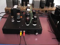
here is my aikido finally finished and feeling at home in a for what i think a nice cherry wood housing.
4*6sn7 2*250v w ct 38v drop across r17 (1500ohm) and janus shunt.
it is dead quiet with the pcb ground tied directly to earth from iec inlet.
the sound in combination with the moskido is magic, i have yet to hear a better combo and that is without burning in of the tubes of the aikido.
pics,
An externally hosted image should be here but it was not working when we last tested it.
An externally hosted image should be here but it was not working when we last tested it.
An externally hosted image should be here but it was not working when we last tested it.
I meant to ask you about C23. I see that you have it installed. I can't find any schematic or user guide that has a value or literature about it. I thought maybe it was for a headphone Amp but I noticed you have it setup for a lineamp.
Last edited:
You mean the Tetra sans psu?Tetra sans phono
Hard to tell. I can't find the max current the Janus can supply.
Hi,
I'm new here.
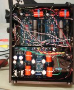
I've assembled the aikido Dual Octal mono boards with the Janus Shunt regulator. I'm only getting a very very faint signal out of unit that is not dependent on the volume pot but otherwise no sound. I'm running a quad of 6SN7's, my readings seem to be in line with the manual. I have wired it as a full wave voltage doubler. I've wired the 6SN7's in series.
The B+ is 325vdc
I'm getting 12.6 vdc across H- H+
H+ to ground is 80 vdc
H- to ground is 80 vdc
The filaments on the 6SN7s do not glow and are cold to the touch.
I had a few missteps along the way, first wiring the 6SN7's in parallel and wiring the heaters center taps to the pad and getting a bit of an arc at warm up with the variac. (shorting to the cap s body?) I've since pulled the green heater CT off the pad and capped it off.
I am confident in my part install and grounding ect... somehow I think the problem lies with the heaters but I'm stumped?
any advice would be appreciated.
Cheers,
Kirk
I'm new here.
I've assembled the aikido Dual Octal mono boards with the Janus Shunt regulator. I'm only getting a very very faint signal out of unit that is not dependent on the volume pot but otherwise no sound. I'm running a quad of 6SN7's, my readings seem to be in line with the manual. I have wired it as a full wave voltage doubler. I've wired the 6SN7's in series.
The B+ is 325vdc
I'm getting 12.6 vdc across H- H+
H+ to ground is 80 vdc
H- to ground is 80 vdc
The filaments on the 6SN7s do not glow and are cold to the touch.
I had a few missteps along the way, first wiring the 6SN7's in parallel and wiring the heaters center taps to the pad and getting a bit of an arc at warm up with the variac. (shorting to the cap s body?) I've since pulled the green heater CT off the pad and capped it off.
I am confident in my part install and grounding ect... somehow I think the problem lies with the heaters but I'm stumped?
any advice would be appreciated.
Cheers,
Kirk
Attachments
Hi, Thanks for the response. On the pins #7 #8 of the sockets: I'm getting 81vdc to ground. but I get nothing measuring across Pin #7 to pin #8.There must be another jumper on the board. If you're getting 12.6V at the H+//H- terminals then can you check at the heater pins on the sockets.
Its nearly the only explanation if the valves aren't heating.....
Fran
(again, they are wired in series)
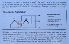
I've noticed a small typo in the user guide page four "Filament Jumper Wire schedule", pins #7 and #8 seem reversed on the diagram. H- actually connects to Pin #7 of the V1, here's a link to the manual, page four;
www.tubecad.com/Product_PDFs/Octal_Mono_C.pdf
Is this an issue?
I'm also using 3300uf cap on C4 that was supplied with the kit, 100-1K uF is recommended on the parts list.. I don't see this as a problem.
I've checked all the resister placement and confirmed their values. I believe I've got all the jumpers in place, J1 -J2, R-17.
I do have a question about the LM 350 regulator: what would be a sign it has failed?
Again,
Thanks for your assistance.
Kirk
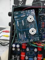
OK, so you should have a wire link in for J4, but J3 and J5 left open? See pg4 of the linked manual. The manual only shows the topside too - whereas we are looking at the bottom side in your photo. Can you double check you have the right manual?
I don't think your regulator is gone as you have 12V at the H+/H- pins - its more likely that there is something wrong with J4 than anything else. Check the jumpers again - and one thing - you'll get 12.6V at the H+/H- pins, but nothing across pin 7&8 if you don't have the valves in. Could you have a bad connection on one of the valves, or a poor connection at the socket?
Measuring the 81V to ground is OK - the heaters are elevated above ground and that sounds about right.
Fran
Yes I've jumped only J4.OK, so you should have a wire link in for J4, but J3 and J5 left open? See pg4 of the linked manual. The manual only shows the topside too - whereas we are looking at the bottom side in your photo. Can you double check you have the right manual?
I don't think your regulator is gone as you have 12V at the H+/H- pins - its more likely that there is something wrong with J4 than anything else. Check the jumpers again - and one thing - you'll get 12.6V at the H+/H- pins, but nothing across pin 7&8 if you don't have the valves in. Could you have a bad connection on one of the valves, or a poor connection at the socket?
Measuring the 81V to ground is OK - the heaters are elevated above ground and that sounds about right.
Fran
My manual is revision E, but I believe the only difference is the latest revision has printing on both sides of the board so you are able to mount components on the bottom and mount the tube sockets on the top. The heater diagram is the same for both
I pulled the valves, the readings I get between vary whether using either the positive or negative probe between pins #7 & #8, 0.12 vdc ect.... not 12.6vdc, and I still get 81vdc pin to ground on all.
I've re-flowed the solder on the sockets and checked continuity between pad and pin. All are good.
Could I have damaged the valves in all my trials? they check good on my tester and indeed the filaments glow while testing.
Again thank you for your time.
Kirk
Attachments
hi, re-read your suggestion, resoldered all the pins ect..., Took readings WITH the valves in, still no voltage between pins #7 & #8 here is a page from the manual with how my filaments are jumpered ( highlighted in yellow). Is this correct?OK, so you should have a wire link in for J4, but J3 and J5 left open? See pg4 of the linked manual. The manual only shows the topside too - whereas we are looking at the bottom side in your photo. Can you double check you have the right manual?
I don't think your regulator is gone as you have 12V at the H+/H- pins - its more likely that there is something wrong with J4 than anything else. Check the jumpers again - and one thing - you'll get 12.6V at the H+/H- pins, but nothing across pin 7&8 if you don't have the valves in. Could you have a bad connection on one of the valves, or a poor connection at the socket?
Measuring the 81V to ground is OK - the heaters are elevated above ground and that sounds about right.
Fran
Cheers,
Kirk
Attachments
Yes, thats correct. So what happens if you put the negative probe of the meter on H-, then put the positive probe on:
pin 8 of V1
pin 7 of V1
pin 8 of V2
pin 7 of V2
with the valves in. This traces the circuit around the board and you should be able to see where the break in the circuit is. Its very unlikely you burnt out the filaments on the valves.
Just something else to be sure of. With no valves in, and powered up, you are getting ~12V at the H+/H- pins. Are you still getting ~12V when the valves are in? (this is just checking to see if somehow the load is dropping the voltage.
Lastly I see from your pic you have the dual mono boards. Are you seeing exactly the same thing on both boards?
Fran
Hello,Yes, thats correct. So what happens if you put the negative probe of the meter on H-, then put the positive probe on:
pin 8 of V1
pin 7 of V1
pin 8 of V2
pin 7 of V2
with the valves in. This traces the circuit around the board and you should be able to see where the break in the circuit is. Its very unlikely you burnt out the filaments on the valves.
Just something else to be sure of. With no valves in, and powered up, you are getting ~12V at the H+/H- pins. Are you still getting ~12V when the valves are in? (this is just checking to see if somehow the load is dropping the voltage.
Lastly I see from your pic you have the dual mono boards. Are you seeing exactly the same thing on both boards?
Fran
Thanks, my results have been a bit erratic and odd.
The simple answer is when I put the negative probe on H- and the positive probe on the #7 & #8 pins I get: 0.00 VDC
but when I drive the positive probe lightly through the coating above the traces right before the pin pad I get erratic readings of anywhere from -0.24vdc to -0.75 vdc, these seem to change each time I power up and down.
My first thought was the traces are not making contact with the socket tabs, but after re-flowing the solder again and testing for continuity to the traces it seems they are.
I am perplexed, I'm not a total novice I've built a few kits and I've done many point to point refurbs but this has got me stumped, Your help is appreciated.
Again thanks for your time.
Cheers,
Kirk
Yes, its sounding great. I didn't mean to flame JB and the manufacture of his boards, after thinking about it I realized that in the capacitor C-4 slot I had installed some larger audiograde caps whose leads were a bit to thick. I lightly worked a bit of wire in and out of the pad to expand the hole and must have cracked the trace, hence the intermittent readings of continuity.....since it was happening on both boards is what was confusing. Thanks for you help Fran!Great! OK glad it worked out!
So glad you should have sound now?
Fran
Attachments
- Home
- Amplifiers
- Tubes / Valves
- Building a Aikido preamplifier