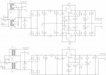
Nothing really special! Based on this notes I replaced R2 with a low noise 13V Zener for +/-15V (actually +/-14,25V) and two green LEDs for 5V and try to have a good layout wrt ground. Pots R8-R10 are optional!
Attachments
Last edited:
Thanks @mull3t and @curryman. Great info. Simple is good. I'll wait for your testing on the Traco SMPS.
@curryman: What are the current max load consumption values for the Buffer and DAC? I'm pumping numbers into the Salsa BiB calculator to see I can understand that build just in case I go that route before the GB closes.
Cheers
@curryman: What are the current max load consumption values for the Buffer and DAC? I'm pumping numbers into the Salsa BiB calculator to see I can understand that build just in case I go that route before the GB closes.
Cheers
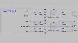
You'd need max. 65mA for the 5V supply and max. 35mA per Rail for the buffer supply. The buffer current depends on the properties of the actual Fets used but with 35mA you are quite save. You might want to add some for the shunt but I wouldn't go too high ")
Please find attached the Filter for the Traco SMPS Joachim tested.
regards, Daniel
Please find attached the Filter for the Traco SMPS Joachim tested.
regards, Daniel
Attachments
Thanks Curryman.
The BiB guide says: "Its good to spare current in the regulators if you have the sinking surface, it enhances the performance. 70-150mA excess on top of max load demand is usual practice for normal operation."
The spreadsheet says: "Constant current sourced by Q101. It should provide at least the current consumption by the load plus some headroom for proper functionning of the shunt reg and peak transitories (with a minimum of 25mA or 20% more than the load as a starting point) YMMV."
Taking your advice to not go too high, I'm going to add the minimum 25mA to both the 65mA and 35mA values which adds roughly 39% and 71% more respectively. The typical 70-150mA excess headroom outlined in the guide sounds like too much based on your comment. Sound right? Much appreciated. Cheers.
Ready to use DAC boards are now available!
@Boomer2: the headroom is subject to quite controversal discussions. I've seen people reporting of amazing improvements using more than 1A of headroom for systems with a max load current of below 100mA. Not sure if I can hear those improvements
The load current of the output buffer is constant so there is no need for a big headroom from a technical point of view. With 50-60mA per rail you'll be on the save side. The 65mA is a max. value and adding 25mA will be more than sufficient here too. "High" current demand e.g. of the XO will be handled by the local decoupling caps anyway (regs are way too slow!).
@ all: I am happy to announce the availability of the ready to use boards. Please have a look into the vendors forum for more info.
Regards, Daniel
Daniel at al,
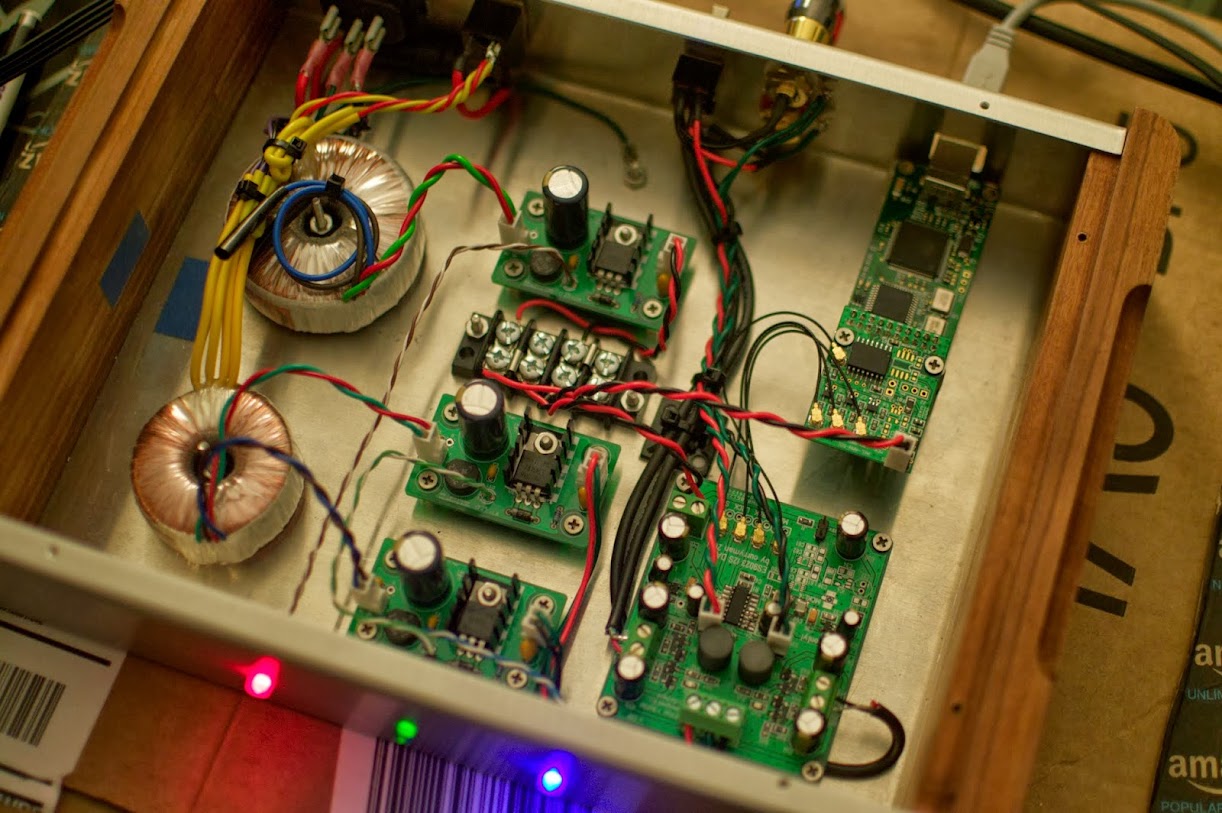
I've finally completed building my Curryman 9023! As usual, I'm running into a major issue with muffled and distorted audio and I'm not really sure where to start troubleshooting beyond initial power voltage readings. I'll detail how I have my configuration set up so things are easier to understand...
I'm using 3 power supplies all designed by AMB audio. The model of the supply is the Sigma 25. The first power supply is providing 5v to the DAC board and to an Acko S01 Isolator / Re-clocker board. The supply is connected to a terminal strip which then connects to the two separate boards. I'm reading +5v in to both boards and 3.3v or 3.6v after their respective LDO regulators (DAC, XO, and power for re-clocker board). The other two supplies are connected together to provide +/- 15v for the JG Buffer. I'm getting a reading of +/- 15v for this supply. So it looks like my power is in order.
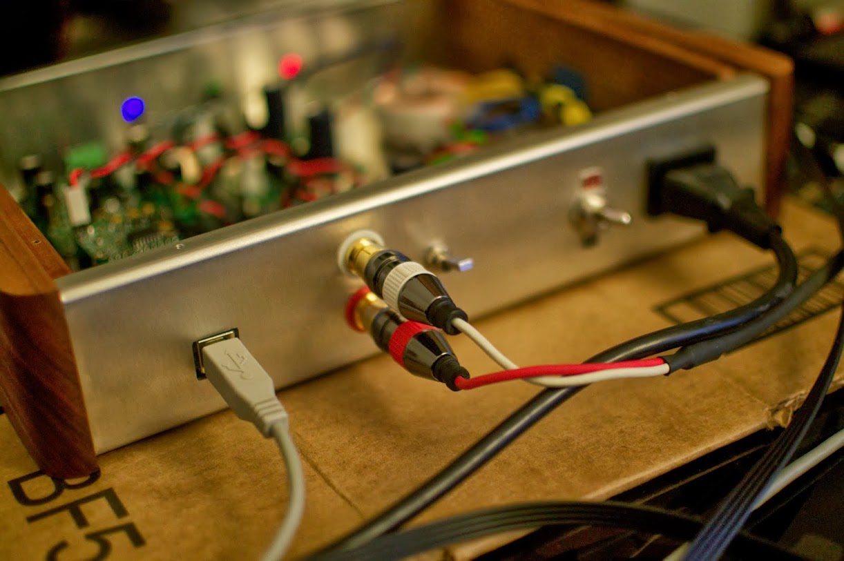
In my particular configuration I decided to go with a pre-buffer / post-buffer switch. I'm using a DPDT switch that is only taking in the left and right channels of audio. No ground connections. Then my ground connections (all 4) are hooked directly up to my RCA terminals. So I'm not switching GND. Just L/R. This way I only need one set of RCAs.
I'm getting the noise, distortion pre and post buffer so the issue seems to be before the buffer.
The way I set up the XO and re-clocking is this way. I have the XO on board which feeds the re-clocker RCK and then the SDATA, LRCK, and BCK are feeding back into the DAC. So the on-board Clock is acting as reference for the re-clocker.
There are only two things that come to mind to be the issue... either the DAC chip or something is wrong with the re-clocker board.
Any ideas are appreciated.
~Mull3t
I've finally completed building my Curryman 9023! As usual, I'm running into a major issue with muffled and distorted audio and I'm not really sure where to start troubleshooting beyond initial power voltage readings. I'll detail how I have my configuration set up so things are easier to understand...
I'm using 3 power supplies all designed by AMB audio. The model of the supply is the Sigma 25. The first power supply is providing 5v to the DAC board and to an Acko S01 Isolator / Re-clocker board. The supply is connected to a terminal strip which then connects to the two separate boards. I'm reading +5v in to both boards and 3.3v or 3.6v after their respective LDO regulators (DAC, XO, and power for re-clocker board). The other two supplies are connected together to provide +/- 15v for the JG Buffer. I'm getting a reading of +/- 15v for this supply. So it looks like my power is in order.
In my particular configuration I decided to go with a pre-buffer / post-buffer switch. I'm using a DPDT switch that is only taking in the left and right channels of audio. No ground connections. Then my ground connections (all 4) are hooked directly up to my RCA terminals. So I'm not switching GND. Just L/R. This way I only need one set of RCAs.
I'm getting the noise, distortion pre and post buffer so the issue seems to be before the buffer.
The way I set up the XO and re-clocking is this way. I have the XO on board which feeds the re-clocker RCK and then the SDATA, LRCK, and BCK are feeding back into the DAC. So the on-board Clock is acting as reference for the re-clocker.
There are only two things that come to mind to be the issue... either the DAC chip or something is wrong with the re-clocker board.
Any ideas are appreciated.
~Mull3t
Noise/distortion
same problem when you turn down digital volume level to say 60%? If it clears up [raw out of the DAC no FETs] when you turn down digital gain, that is simple. Leave gain down, or pick different resistor other than the ~200K... ODAC used 118K for instance, on the Vreg? pin? [it's been a while]
And, obviously, try a simple direct I2s source, even something cheap like a Ti PCM270# or TE7022...
I gather you have placed an O-scope on the voltages and taken a peek there?
I have DAC chips for you, but I doubt your fried it. I'm in the USA.
I'm not at home to test going to a lower digital volume, but it's worth a try. I don't recall what I used for the resistor. I think it was 200k though. The Vreg pin is what R8?
I don't have access to an O scope. Maybe I can scrape one up somewhere. I'm in a work environment that would potentially have one. I do have a DMM so if there's any extra voltages that I should measure that would be helpful.
I do have two extra DAC chips in case. I could have fried it. I accidentally had applied reverse polarity for maybe a minute or so... maybe less. Would haven't my LDOs been fried in the process?
I am not up on LDO design, the basic VOM would say if it's outputting something perhaps correctly, but a scope set down on very low AC range would tell you about noise or lack thereof. At least in my old days servicing early 80s gear, a scope would show when the rails were dirty, like a cap out or some sort of unwanted noise, but, it helps to know what is normal ambient noise at a given setting...[looking at the PSU rails] you don't know that.
I would start super super simple, run the DAC at 3.6V [or 3.3 if you have any other simple regulators around], use a simple 4-wire+gnd 16/44.1 whatever I2S source... or your clock on MCK...whatever. Not FETs, no Reclock, no Amanero... [cut the potential problem source in 1/2 basically].
I don't know HOW distorted your audio is. If it cleans up at 60% digital gain then you have a simple problem. If it's rough going no matter what, try JUST the DAC as above?
By the way, I found some cheap ES9023 directly from DIYINHK's site not eBay, I would I could loan you one for testing...they were sub-$20USD and they got shipped air. Sounds like you STARTED with a somewhat elaborate complex mixture of building blocks...which is great, but.
Did you try anything "vanilla" before getting fancy? Or direct jump into deep end of pool? Meaning no offense, I know I like to tinker, plot out the best I know how...
Once when I miswired i2s I had not music really, some remote hint of music but 98% odd noise/hash. Do you hear music but poor quality with some "ripping" and breaks of linearity?? Or REALLY screwed up? I know you seem to have ruled out the buffer.
DO you own any other USB DACs that you can borrow I2s from? Seat of pants I would try like 50r in series with each I2S line...[even if you shorted it it might survive] and carry also your GND over.
Yah that 200-220K if your sound is fine at 50-60% digital gain, try 100K or 120K there. Pin 6 ES9023
See here: http://www.yoyodyneconsulting.ca/downloads/General/ODAC/ODAC-release.pdf
Good news! I have access to a scope at work. I'm going to bring in the DAC on Monday and have a co-worker help me out with the scope. Never really used one.
I hear music -- it's definitely poor quality. The distortion causes the bass to be over accentuated and there is a hissy scratchy type noise in general. Like I said it's certainly distorted. It doesn't clear up when lowering the digital volume. I do have an extra Amanero on hand that I can use for experimentation. I was planning on using it for a future project but I guess this situation might require it. This is the best I got in terms of alternate USB -> i2s transports.
I wanted to be ambitious with this project and figured it would be a nice jump from the AMB Gamma 2 and somewhere in between that and a Buffalo III. I just jumped into the pool per se. I've built a bunch of smaller USB DACs with SMD in the past so this seemed like it wouldn't be too much of a challenge.
Here is a list of readings that I've taken so far...
4.97v coming into DAC board.
3.274v from LDO 3V3.
3.579v from LDO 3.6
1.67v - MCLK out of DAC to re-clocker.
1.109v out of Pin 6 (Vreg).
At IDLE L channel is .143v
R channel is .267v
AVCC - 3.579v
CP - 1.648v
I'm not getting any reading on NEG, C201, etc.
The last readings worry me a bit. I did use the alt 10nF caps on C2 and C3. I'm thinking of removing them to see if things get better.
Thanks for the help!
did you use a beta board or the later RARE real release version of the ES9023 // JG buffer DAC board? I have not seen a schematic or the real board layout in 6+Mo even though I own more of the beta boards than anyone on the planet, hah.
Sounds like you have a complex situation that I would try to cut in 1/2s or 1/3's until the problem is fleshed out.
I would set aside all but the essentials. So-so regulators should still yield un-fractured sound IMHO... My experience with isolators etc is quite limited but I will say that in the 44/96 world a fiber-optic isolator has been dreamy. The USB-> I2S world has far surpassed the bandwidth of what I own for isolation, 480 I cannot do. I digress. I have maybe 10 fiber USB isolators left Opticis...PM me if you want one.
PM me if u are using the beta board? a cap might be hmm, wrong setup?
Success! I removed the additional cap that is listed on the v1.1 schematic at position C2 - 2.2uF + 10nF.
http://www.diyaudio.com/forums/vend...ut-dac-incl-jg-filter-buffer.html#post3644393
Here's a pic of what the caps look like soldered in place for C2 and C3.

After removing the 10pF cap, I still was having issues with just the 2.2uF cap so I removed it and resoldered it and all is well. Now I have no DC offset and no distortion. Everything sounds great! Not sure what I'm missing sound-wise without that extra 10pF cap at C2.
I suppose I have one of the RARE real release boards. I also have one of the beta boards that you sent me. I plan on using that in the future sometime when I want to do full sync with the Amanero as slave to the Acko S03 board.
http://www.diyaudio.com/forums/vend...ut-dac-incl-jg-filter-buffer.html#post3644393
Here's a pic of what the caps look like soldered in place for C2 and C3.
After removing the 10pF cap, I still was having issues with just the 2.2uF cap so I removed it and resoldered it and all is well. Now I have no DC offset and no distortion. Everything sounds great! Not sure what I'm missing sound-wise without that extra 10pF cap at C2.
I suppose I have one of the RARE real release boards. I also have one of the beta boards that you sent me. I plan on using that in the future sometime when I want to do full sync with the Amanero as slave to the Acko S03 board.
Good to hear that you got your board running! Your picture shows the v1.08 board with 2.2µ + 10n at C2 and C3, so before removal, right?
It always worked for me quite well with both caps but it's indeed quite fiddly. Maybe you had a short at C2 (it looks a bit like there is some solder under the brown cap). Anyway if it works now it's fine
The difference with/without is indeed very small so I would not care too much
regards and happy listening, Daniel
Yes this photo was before removal. If it's of no consequence removing 10nF cap from C2 then I'm game. It's not easy to solder it into position. I did notice after removing the 10nF cap that I'm getting a reading of -3.357v for NEG. Do you reckon that figuring out a way to get that cap back in place would get me closer to -3.6v? I'm thinking an easy way to do it is to mount it bottom-side between the leads of C201.
Daniel... by the way, thanks for making a really fun and great sounding project available.
Daniel... by the way, thanks for making a really fun and great sounding project available.
Last edited:
 Currently I am only using an isolator...
- Status
- This old topic is closed. If you want to reopen this topic, contact a moderator using the "Report Post" button.
- Home
- Source & Line
- Digital Line Level
- Build thread for ES9023 + JG Buffer boards (betatest)