I've been wondering a while now what would happen if you simulcast I2s? Literally Y off the signals and feed to another DAC via maybe 50 ohms each leg? OR, use a 4PDT PCB relay [I bought some a year ago]. Example might be a tiny PCM5102A board [on the net $29.99? USD DIYINHK.com], or, AK4399 or... well, ES9018 would not be "tiny". I was wondering for a different reason, wondering if I can drop ES9023s into a Behringer DCX2496 without ripping the stock AKM DACs out? Then I would have single-ended outs and bypass a ton of junk on the stock output board. No time to try that YET -- maybe this Winter? I also wanted to try a ES9023 in my Brother-in-law's Musiland MD30 which he doesn't like -- not wrecking the stock apparatus to try it. I suppose a Y in the I2S would not be brilliant? And the relay probably causes it's own problems - worth a try though. Can't decide which DAC you like for a given kind of use or music? Flip the switch 8)
IPX / u.fl toIPX / u.fl 1.13 cable 15cm
^^^ might be one place to get pre-made u.fl cables? ^^^
IPX / u.fl toIPX / u.fl 1.13 cable 15cm
^^^ might be one place to get pre-made u.fl cables? ^^^
@Ryssen - I bought them at Mouser... 415-0085-100 Johnson / Emerson Connectivity Solutions | Mouser
They look to be backordered at the moment. Looks like enjoybiking has found a better deal.
@curryman - At the moment I'm thinking that to my rather semi-old and tinny ears, the buffer takes the edge off, but very slightly. Also, I'm hearing slightly more detail with the buffer on. When I say slightly I mean slightly. I did the pre/post buffer to see if there is a huge difference and to my ears there isn't. Hopefully, others have tried a similar configuration and can offer their opinion.
@enjoybiking - I like your ideas about switching between 2 DACs. I've been curious whether there is some sort of device that takes in i2s and spits out multiple outputs. I'd be interested to hear about your findings.
I am WAY behind on my DIY "professional development" -- what ICs do the reclockers use?
I own a huge reel of something like 2500x 74VHC04MTC. Could they be employed? I2S {minus MCK}, feed remaining 3 signals into 2 inverter inputs EACH/ at once? [one inverter per I2S line per DAC] Don't bash me, I don't know...this is DIY.
http://www.ic-on-line.cn/download.p...145F0A24146F31&file=0112\74vhc04m_1185399.pdf
^^^ link to PDF ^^^
The ES9023 with it's own 50.000MHz clock, and Ti PCM5102A also needs no MCK, right? Just examples.
I probably have regulators, LT1761 3.3 or some Micrel 5V... I don't know if cramming I2s into 74VHC04MTC would degrade the signals, or, actually clean them up? Or would a few simple 50 ohm resistors in series with Y's of the I2S signals suffice? Or the 4PDT DIP relay? A panel switch could operate the relay and also switch WHAT DAC output goes to the RCAs. Maybe the relay contacts on a sweep spectrum analyzer would show a nightmare, I do not know what freqs the I2s lines run at, I know I could look them up. Guys like Daniel just "know" this. One could go pretty nuts and have a rotary selector-switch and whatever relays or inverters...or buffers [with "inhibit"??]. I remember when my Brother-in-law and I were trying to compare Wm8741, WM8761, cs4398... AK4396, and later ES9023, unhooking all that and trying to cleanse one's
palate [beer probably]..."how DID that sound before we switched"? Add say a PCM5102A and whatever filter switches for THAT...[pins #10 & 11], possible a reset sw?
Could inject PCM5102A into the JG Buffer TOO [it probably doesn't need the FILTER but...it wouldn't hurt?]
NO time right now to touch an iron, but I can dream and maybe someone will beat me to it. There might be some room in your chassis yet Mull3t ?
I think THIS is where I got my 4PDT relays for the test:
DS4E-S-DC5V - 4PDT 5V 2A DIP Relay
@enjoybiking - the Acko re-clocker board AKL-AMN-S01/S02 is two boards for the price of one. The S01 and S02 both use the NVE715-3E 4CH DIG Isolator and iL711 2CH DIG Isolator. The iL711 is not needed if you're not going to use the Amanero as slave to external clocking. The S01 uses the 74AUP1G79GV 1CH FF. I just used 3 of them because I didn't need to re-clock MCLK. The S02 uses 2 Potato Semi flip flops... PO74G74A. The S03 also uses the PO74G74A. Not sure if your current parts match up with these. I'm sure your regs do though.
I was under the impression that the 9023 needed an ext. clock -- at least an on board one. If you did external clock board like Acko's AKX302 you could feed multiple MCLK out. It even has a /2 and /4 divider on there. I don't think he is offering it anymore though -- only the AKL-AMN-S03, which has the clocks and re-clocking integrated into one board.
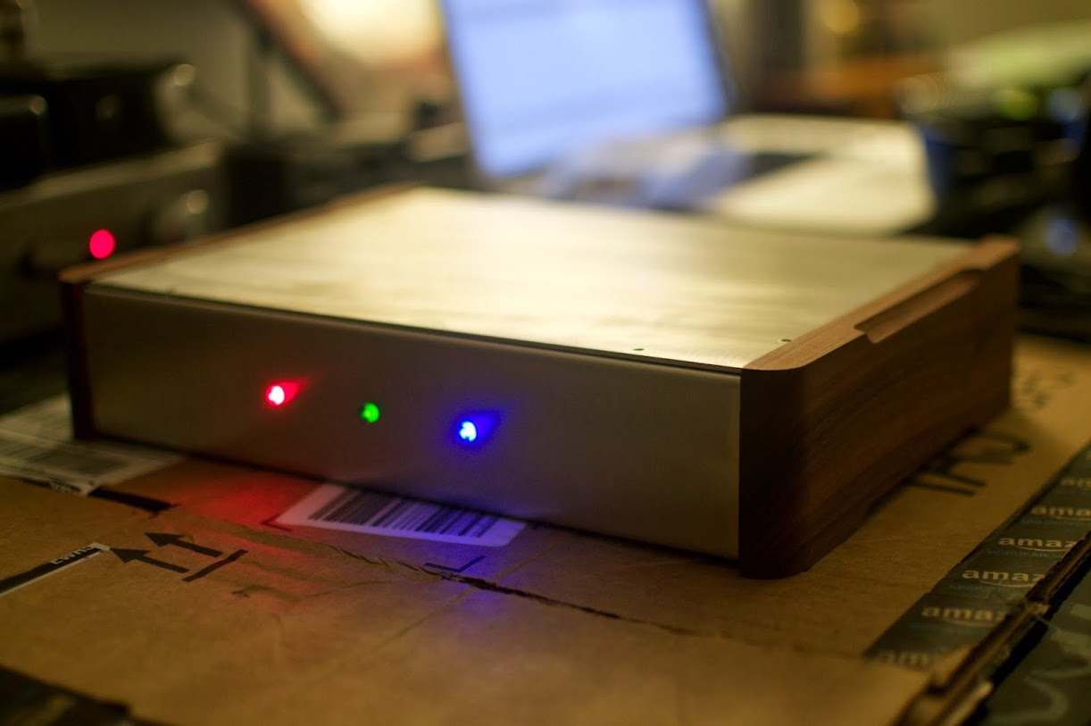
I could fit more into this chassis if I really wanted to, but it would be tight and would take some rearranging. I kind of like how everything is clean and tidy in there though.
Anyways, I think we're getting off the path a bit. Maybe it's time for a beer to cleanse the palate.
I was under the impression that the 9023 needed an ext. clock -- at least an on board one. If you did external clock board like Acko's AKX302 you could feed multiple MCLK out. It even has a /2 and /4 divider on there. I don't think he is offering it anymore though -- only the AKL-AMN-S03, which has the clocks and re-clocking integrated into one board.
I could fit more into this chassis if I really wanted to, but it would be tight and would take some rearranging. I kind of like how everything is clean and tidy in there though.
Anyways, I think we're getting off the path a bit. Maybe it's time for a beer to cleanse the palate.
Yah, beCause the 9023 board setup has MCK covered by an OSC... both the 9023 board and the PCM5102A board would not need MCK. [integrated PLL]. 3-wire I2S and GND. I still have some Bragi <sp> boards around, Christian's IL715/Es9023 design. No time yet. I have the parts too, somewhere. I've been thinking about using recycled or repurposed chassis; I own lots of gear that has room inside for a DAC or two, and cords and switches... A working rackmount BBE system for instance. But the real question is the DCX2496? If I can plunk in some of Daniel's boards, I think I'd have a treasure. Not quite; that takes SPDIF in.. I'd want to try to inject I2s, plunk a USB-I2S board in. I've been wanting a universal tri-amp setup for a decade, to play with this and that speaker ideas. LQQks like Daniel did it with items from MiniDSP.
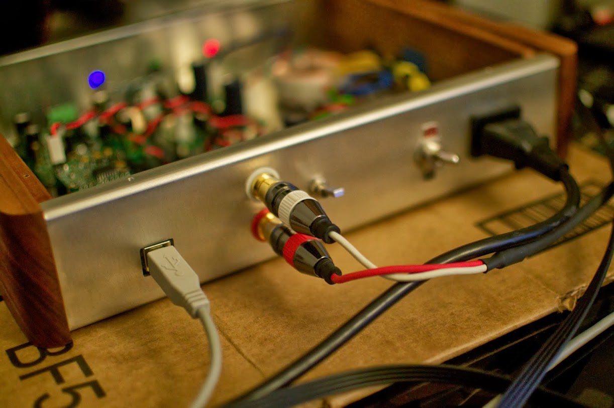
YOUR DAC is awesome! How did you cut the USB hole? DO they make a Greenlee punch for that? as a younger DIY all I had was a drill and a file.
YOUR DAC is awesome! How did you cut the USB hole? DO they make a Greenlee punch for that? as a younger DIY all I had was a drill and a file.
I used the Acko AKL AMN-S01. I then did what Acko called P-Sync or pseudo sync. The on-board clock feeds the re-clocker board and the dac chip. I'm going to eventually do an ES9018 based DAC with full turbo sync and AKL AMN-S03 board.
Hi Mull3t,
Sorry for off topic a bit, I am having a similar configuration as yours
DAC - WM8804 9023 Subbu DAC, clocked by 50MHZ crystal, power by the subbu 5V regulated PS
JG buffer - Power by a +/- 12V Super reg
Amanero - Bus power, still using the same firmware when I bought it last year
Acko isolator/reclocker S01 - not yet build
Everything works fine when using SPDIF input, only when I use the amanero as transport feeding from my pogoplug & Vertoxbox PC input via I2S connection to the dac, once a while I can hear this short glitch sound, never happen on SPDIF. Have you experience such thing with the amanero ? Could this be a unlock issue ?
No glitches so far with Amanero. I get this sort of thing all the time with my Gamma-2 DAC that is using Tos-Link SPDIF. It's like a really short glitch. I think it's an unlock for some reason. In my case, I think it's my software "Decibel" on the Mac that is the cause. When I change "Adjust Sample Rate for Best Quality" setting to un-checked the glitch goes away. In your case I think something else is going on. I'm curious with re-clocking if your problem will go away.
So here we go... pictures! This is what I was able to accomplish with the help of a bunch of people in the forums...
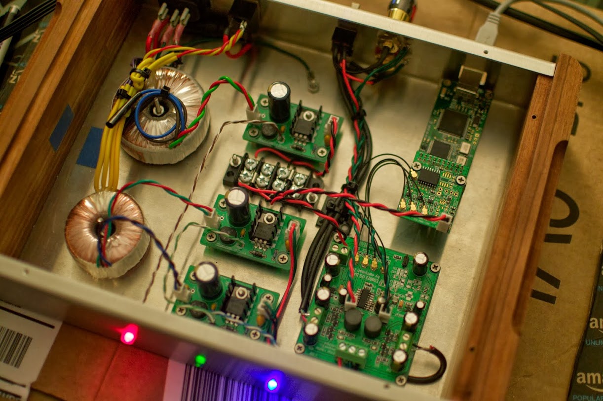
What a nice build ! I don't recognize/know the power supply boards. Which are they ?
A gent on eBay makes these. Actually sad story; the gent who made these originally died suddenly and early. A long time childhood friend picked up the work. I've used many of his cases - solid work.
EDIT: Sorry, can't figure out how to get this link to behave. Go to eBay, user is "01robo".
EDIT: Sorry, can't figure out how to get this link to behave. Go to eBay, user is "01robo".
Last edited:
I'm a big fan of those chassis. Slow down there MisterRogers! Might use one for my next project the EHHA Rev A. And my next after that - An i2s Subbu DAC. ")
@jean-paul - I used the Sigma 25 from Amb.org. For the size/price, they really seem to perform well. I'm sure the Salas BiB is a higher performer, but for this project the Sigma 25 did the trick.
@jean-paul - I used the Sigma 25 from Amb.org. For the size/price, they really seem to perform well. I'm sure the Salas BiB is a higher performer, but for this project the Sigma 25 did the trick.
Last edited:
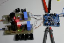
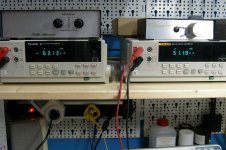
I measured the dc-offset of dac.
The measuring done with 2 Salas regulated to ±15Vdc and 5V from my DP832 Power Supply without any input signal.
Unfortunately, the man who constructed this doesn't much well the fet's.
As you can see, the left output has -63.13mV and the right output has 51.18mV.
Respectively the ESS-9023 output was -1.2mV the left and 2.75mV the right.
I am thinking to study the Daniel's method of fet matching and to replace all of them.
Attachments
Hi lemon,
indeed it seems there was some missunderstanding at the manufacturer how to proper match the FETs although I provided a detailed instruction. Me and friends built more than 20 DACs and all had a DC offset below 5mV. I am in contact with miniDSP and we are currently working on this issue.
I'll keep you informed...
BTW: what would you think is a acceptable/expected DC offset (keep in mind the cost of the board)?
regards, Daniel
indeed it seems there was some missunderstanding at the manufacturer how to proper match the FETs although I provided a detailed instruction. Me and friends built more than 20 DACs and all had a DC offset below 5mV. I am in contact with miniDSP and we are currently working on this issue.
I'll keep you informed...
BTW: what would you think is a acceptable/expected DC offset (keep in mind the cost of the board
)?regards, Daniel
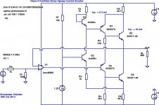
I believe Ken's Diamond (basically a BJT buffer derived from the Taylor follower) probably outperforms the JFET buffer, open-loop - here's the key post that defines the topology:
http://www.diyaudio.com/forums/soli...-buffer-power-output-stage-9.html#post2056889
I did some minor changes in simulation (flipped polarities of all actives) and added an opamp to imcrease the loop gain as well as servo out the offset - the opamp is optional, but it greatly enhances the performance. In practice, a low-rail or rail-to-rail opamp would work best at the +/- 3.6 V rails available from the ES9023, instead of the LME49860 shown in the LTSpice simulation schematic shown below.
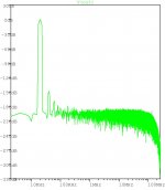
At 1.5V into 600R, THD20 is ~ -150 dBr with the opamp in the GNFB loop. Without the opamp, and the buffer running open-loop, THD20 is still respectable at ~-80 dBr at 1.5V into 600R.
http://www.diyaudio.com/forums/soli...-buffer-power-output-stage-9.html#post2056889
I did some minor changes in simulation (flipped polarities of all actives) and added an opamp to imcrease the loop gain as well as servo out the offset - the opamp is optional, but it greatly enhances the performance. In practice, a low-rail or rail-to-rail opamp would work best at the +/- 3.6 V rails available from the ES9023, instead of the LME49860 shown in the LTSpice simulation schematic shown below.
At 1.5V into 600R, THD20 is ~ -150 dBr with the opamp in the GNFB loop. Without the opamp, and the buffer running open-loop, THD20 is still respectable at ~-80 dBr at 1.5V into 600R.
Attachments
Thanks for the feedbackand good to hear that you like the sound
While the DC should not be a big problem if the amp is ac-coupled (capacitor or servo) I am wondering a bit about the quite high values. I build more than 10 DACs myself and always had below 10mV (most are 2-4mV). I'll check this with the manufacturer.
The 0 Ohm resistors are R46 and R56, however adjustment only works in one direction. So if you have a small negative offset (e.g. -50mV referenced to ground) you can use a small pot (you'll need approximately 10 Ohm for 50mV) instead of the jumpers to adjust the DC offset.
regards, Daniel
Hi lemon,
indeed it seems there was some missunderstanding at the manufacturer how to proper match the FETs although I provided a detailed instruction. Me and friends built more than 20 DACs and all had a DC offset below 5mV. I am in contact with miniDSP and we are currently working on this issue.
I'll keep you informed...
BTW: what would you think is a acceptable/expected DC offset (keep in mind the cost of the board
regards, Daniel
The first quote is from another thread "ES9023 I2S Input DAC incl. JG Filter Buffer".
Have in mind the above two quotes, I have some questions for you.
1) What is the appropriate smd variable pot for the position of R46/R56 (not value, but what type)
2) What is the meaning with that "however adjustment only works in one direction". If the one channel has negative offset and the other positive can't they to trim -> 0mV?
3) Is there critical difference if the matching done by pot or by well matching fets?
4) What is the right procedure to match well these fets? Is there any reference somewhere? I am thinking to use the Atlas DCA Pro Semiconductor Analyser for that purpose.
Daniel, I hope so don't misunderstand me for what I wrote that he who constructed it didn't a good job in matching. This is a dac, a cheap one, but this is a dac and the output must to be as possible without dc-offset.
You made well design of course, but the constructor didn't follow your directions or he has confused about these.
It is better to correct this, otherwise it is better to you to give it without the output stage and the diy person to complete this himself, as your directions.
This is my opinion.
1) What is the appropriate smd variable pot for the position of R46/R56 (not value, but what type)
2) What is the meaning with that "however adjustment only works in one direction". If the one channel has negative offset and the other positive can't they to trim -> 0mV?
...
I give the answer to myself
1) there isn't such a small smd pot, it is better to put a Bourns 3296Y type btw 2&3 or 1&2 legs with some mods on legs.
3) the corrections can be achieved only to negative values the positives values couldn't to decreased. I tried two of them and the correction done only to negative place.
Totally, if you have one channel with positive and other channel with negative dc-offset, the better is matching the fets right.
I don't know if it is better to removed the 100R (R55/R45) for example with some smaller e.g 50R and put a pot 100R parallel.
Last edited:
- Status
- This old topic is closed. If you want to reopen this topic, contact a moderator using the "Report Post" button.
- Home
- Source & Line
- Digital Line Level
- Build thread for ES9023 + JG Buffer boards (betatest)