You guys are correct. Assuming a non-zero source impedance makes low filter resistor values a risky proposition and may substantially affect the notch. Unfortunately I did upload the wrong network.
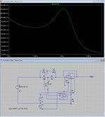
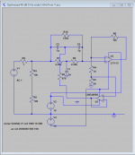
The correct network (see pic 3) has an input buffer that prevents this from happening. I did simulate many filter alternatives with various combinations of opamps and I got the by far the best results (low noise) with filters that had input buffer in combination with lower resistor values (divided by 10 and 100)) and network feedback. That was true for Dick's as well as David's and my combination of the two. David's division by 10 - network went a long way but dividing by 100 together with an input buffer noise was reduced even further. I did use David's network with OPA209 to verify that my IC model and noise results were in line with his.
The network with the lowest output noise was the original filter with 99% lower resistor values and input buffer. Output noise was reduced by about by ca. 75% compared to the original design. The filter that didn't fare that well (in comparison and with equal resistor values) was the 40dB filter with one IC and no feedback (surprising since that that was the rational to reduce noise in the first place).
I tried combinations of several different opamps, all did substantial improvements but OPA211 and OPA209 stood out with the most noise reduction. OPA211 was better with low resistor values and and OPA314 were best with the original higher values. OPA209 was best with resistors values reduced by a factor of 10. The results with OPA1641 were by far the best but too good to be true so I disregarded them for the time being. I probably made a bad translation when I converted TI's TINA file to PSpice format. If anyone has a correct lib-file of this opamp I would appreciate an upload.
Regarding "redundancy" with the feedback IC it is true that as long you want no more attenuation than 40dB you don't need the feedback. However I wanted to retain the flexibility to select a variable notch depth down to 98dB (along with Q-value and frequency tuning) and for that the feedback loop is needed. In addition, as I just discovered, it is also a way to reduce output noise.
In the end I don't think the network with extreme low resistor values is practical for a tunable filter with pots. The precision pots with values 5-10 ohm are hard to find and very expensive. On the other hand I think this is the way to go for a one fixed-frequency network. I'm going to build one to see if I can verify this.
Attachments
If the distortions you are looking for are above -120 then an input buffer like shown works fine but not below. Especially if its used non-inverting. I have been checking the distortion products at the input when connected to various devices and you do see significant (if below -130 can be significant) distortions from the input buffer's input circuit. Some can be from loading the previous stage as well.
You guys are correct. Assuming a non-zero source impedance makes low filter resistor values a risky proposition and may substantially affect the notch. Unfortunately I did upload the wrong network.
The correct network (see pic 3) has an input buffer that prevents this from happening. I did simulate many filter alternatives with various combinations of opamps and I got the by far the best results (low noise) with filters that had input buffer in combination with lower resistor values (divided by 10 and 100)) and network feedback. That was true for Dick's as well as David's and my combination of the two. David's division by 10 - network went a long way but dividing by 100 together with an input buffer noise was reduced even further. I did use David's network with OPA209 to verify that my IC model and noise results were in line with his.
The network with the lowest output noise was the original filter with 99% lower resistor values and input buffer. Output noise was reduced by about by ca. 75% compared to the original design. The filter that didn't fare that well (in comparison and with equal resistor values) was the 40dB filter with one IC and no feedback (surprising since that that was the rational to reduce noise in the first place).
I tried combinations of several different opamps, all did substantial improvements but OPA211 and OPA209 stood out with the most noise reduction. OPA211 was better with low resistor values and and OPA314 were best with the original higher values. OPA209 was best with resistors values reduced by a factor of 10. The results with OPA1641 were by far the best but too good to be true so I disregarded them for the time being. I probably made a bad translation when I converted TI's TINA file to PSpice format. If anyone has a correct lib-file of this opamp I would appreciate an upload.
Regarding "redundancy" with the feedback IC it is true that as long you want no more attenuation than 40dB you don't need the feedback. However I wanted to retain the flexibility to select a variable notch depth down to 98dB (along with Q-value and frequency tuning) and for that the feedback loop is needed. In addition, as I just discovered, it is also a way to reduce output noise.
In the end I don't think the network with extreme low resistor values is practical for a tunable filter with pots. The precision pots with values 5-10 ohm are hard to find and very expensive. On the other hand I think this is the way to go for a one fixed-frequency network. I'm going to build one to see if I can verify this.
How does the third pix look when the bridging network across the IC has the correct value of Caps for the 160 R's you are using? Using David's formula C3 should be .27uF and C4 should be 3.7uF I think. Larry
The "bad" caps I've seen usually show more 2nd harmonic than 3rd, so the CLT-1 might not reveal everything.
Samuel
I got the CLT-1 up and did a quick test. The Tek caps are reading the same as a Component Research Teflon cap in a plastic case with copper leads of a close value.. I'll do some more tests and verifications but I think I'm seeing below -170. The readouts on this need a review of the manual to get right.
I got the CLT-1 up and did a quick test. The Tek caps are reading the same as a Component Research Teflon cap in a plastic case with copper leads of a close value.. I'll do some more tests and verifications but I think I'm seeing below -170. The readouts on this need a review of the manual to get right.
At what level? I've seen some film (both Polypropylene and Polystyrene) capacitor types not revealing any detectable distortion (i.e. they measure -150/-160 dB at +20 dBu drive with my current setup). Unfortunately I have, so far, no clue what separats them from apparently equaly made parts, which however show considerably worse, and very inconsistent distortion performance.
Samuel
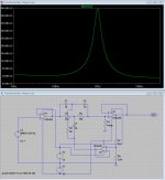
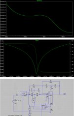
DDE, Attached is the noise curve for the network with exactly the "correct" capacitor values you requested. Yes, they are correct for David's network but not for mine because the filters have different transfer functions. The reason is that the feedback loop through U2 interacts with the overall feedback of the filter and produces a somewhat different result. The depth is now 57dB and the Q is somewhat less. This can be adjusted by varying R4 (depth) and the capacitors C3/C4 (Q) if you want to replicate David's notch.
Nevertheless, the noise curve is on average ca. 90% lower than the original filter (or ca. 20 dB). Converting the noise curve over the 10Hz - 30kHz sqrt Hz range yields a total noise of ca. 5 uV with 1V input for the original filter and 0.5 uV for the low value resistor filter with input buffer. That translates to a noise floor at -106dB vs -126dB. Bear in mind these are all simulated results and I have yet to verify this by building and testing the low resistance filter.
Nevertheless, the noise curve is on average ca. 90% lower than the original filter (or ca. 20 dB). Converting the noise curve over the 10Hz - 30kHz sqrt Hz range yields a total noise of ca. 5 uV with 1V input for the original filter and 0.5 uV for the low value resistor filter with input buffer. That translates to a noise floor at -106dB vs -126dB. Bear in mind these are all simulated results and I have yet to verify this by building and testing the low resistance filter.
Attachments
What is needed to have a very narrow notch or very high Q notch And only 40dB depth?
THx-RNMarsh
You'd have to go to an higher order. Like two or three TT in cascade. Like the bridged T in the Shibasuko 725.
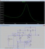
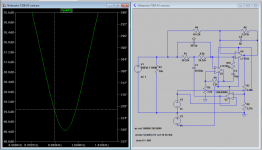
Update on my efforts- I revised the filter circuit as shown in the drawing. Unfortunately I still have excessive 2nd Harmonic distortion from it. The best I'm getting with the active notch is about -135 dB. Switching opamps from LME49990 to OPA209 did not help. The LME49990 in the U2 location did get a 6 dB improvement in noise. If I switch to passive which gets about -65 dB notch depth and then go through all the rigmarole of corrections etc. on the same source (Viktor 995 Hz oscillator running on batteries) I get -142 for the 2nd and -149 for the 3rd. I think these numbers are not far from what it actually is. I'm really disappointed that I can't get better from the active notch. I can try some other configurations to get to the -40 dB notch, maybe.
Attachments
Update on my efforts- I revised the filter circuit as shown in the drawing. Unfortunately I still have excessive 2nd Harmonic distortion from it. The best I'm getting with the active notch is about -135 dB. Switching opamps from LME49990 to OPA209 did not help. The LME49990 in the U2 location did get a 6 dB improvement in noise. If I switch to passive which gets about -65 dB notch depth and then go through all the rigmarole of corrections etc. on the same source (Viktor 995 Hz oscillator running on batteries) I get -142 for the 2nd and -149 for the 3rd. I think these numbers are not far from what it actually is. I'm really disappointed that I can't get better from the active notch. I can try some other configurations to get to the -40 dB notch, maybe.
Your not really putting a gain 100 on U3 I hope. What are you using for an enclosure?
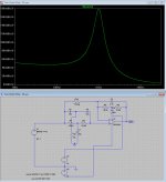
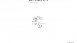
I am and it works! It measures with the LME49990 less than -125 db on the harmonics. I'll check it with the OPA209 that is in there now. That would be a floor with a 40 dB notch of around -165 dB. The idea is to make up the gain lost in the notch. However I don't think this architecture will get me to my goal. However the Shibasoku notch looks like it will. Its more involved and the feedback is more complex but not exceptionally so. I think I can graft it into this setup. See below
Its in an aluminium box with batteries powering it.
Its in an aluminium box with batteries powering it.
Attachments
I am and it works! It measures with the LME49990 less than -125 db on the harmonics. I'll check it with the OPA209 that is in there now. That would be a floor with a 40 dB notch of around -165 dB. The idea is to make up the gain lost in the notch. However I don't think this architecture will get me to my goal. However the Shibasoku notch looks like it will. Its more involved and the feedback is more complex but not exceptionally so. I think I can graft it into this setup. See below
Its in an aluminium box with batteries powering it.
The bridged T is certainly easier to tune. I doubt you need the capacitance canceler unless you're doing measurements up over 15kHz. Below that they don't do much. The null is achieved at the amplifier input. It's a bit touchy getting the null tuned but once you have it, it will stay. I haven't work with the bridged T outside the 339A. I don't know how the distortion will be. In the 339A it's not great.
I think stability of the 40G resistor may be an issue. It may all need to be in an inert atmosphere or leakage will detune it. Not to mention leakage currents from the opamp.
Common mode effects are real but at the notch there is in effect no signal at the inputs so nothing to create common mode.
I will look at reconfiguring the notch I'm playing with to the Shibasoku form. The tuning elements are on a separate board so thats easy. The mix of through hole and surface mount parts make the rework of the main board really difficult.
The cap canceller is to deal with the 30 relays in the Shibasoku. I removed it in the simulation with no effect.
- Status
- This old topic is closed. If you want to reopen this topic, contact a moderator using the "Report Post" button.
- Home
- Design & Build
- Equipment & Tools
- Build -- Active Twin-T notch filter for distortion analysis