the real challenge: ensuring sufficiently low distortion contribution of the notch filter.
As posted elsewhere I have designed a set of decadic passive notch filters, using C0G caps, series-parallel MiniMELF resistors and a variable attenuator (0 dB, 10 dB or 20 dB) ahead of the filter. This has proofed to be suitable for measurements in the -140 dB region (in particular it was used by AP in the development of the new APx555 which was just announced officially today). I hope to implement a few further ideas in a second revision and write a brief text about it once time permits, but if interested I can forward the current Gerber files by e-mail.
Samuel
May I please have a copy of your notch filters?
Thank you,
Richard Marsh
rmarsh@calweb.com
I already did, under every assumed identity I could devise.
As posted elsewhere I have designed a set of decadic passive notch filters, using C0G caps, series-parallel MiniMELF resistors and a variable attenuator (0 dB, 10 dB or 20 dB) ahead of the filter. This has proofed to be suitable for measurements in the -140 dB region (in particular it was used by AP in the development of the new APx555 which was just anounced officially today). I hope to implement a few further ideas in a second revision and write a brief text about it once time permits, but if interested I can forward the current Gerber files by e-mail.
Samuel
Samual,
May I have a copy of your notch filters?
I'm doing some DIY of notch filter for my measurment.
Thank you,
Sky2city
sky2city@163.com
Hi Samuel, I would like to receive the Gerber files of your nitch filter.
c.alviano@alice.it
Thank you very much
Claudio
c.alviano@alice.it
Thank you very much
Claudio
Basically yes, but you can estimate the distortion contribution of the passives and opamp(s) using first-order extrapolations from known measurement points (I think I've posted such a calculation earlier in this thread).
Generally speaking I'd advise against the use of "activated" or tunable notch filters for very low (< -130 dB) distortion measurements as they have more distortion mechanisms which need attention. Correcting the frequency response and using large FFTs to get the noise floor down are rather trivial means compared to the real challenge: ensuring sufficiently low distortion contribution of the notch filter.
As posted elsewhere I have designed a set of decadic passive notch filters, using C0G caps, series-parallel MiniMELF resistors and a variable attenuator (0 dB, 10 dB or 20 dB) ahead of the filter. This has proofed to be suitable for measurements in the -140 dB region (in particular it was used by AP in the development of the new APx555 which was just anounced officially today). I hope to implement a few further ideas in a second revision and write a brief text about it once time permits, but if interested I can forward the current Gerber files by e-mail.
Samuel
Hi Samuel,
I would be interested in the files if you're able to send them. Hoping to test with some of Victor's oscillators.
crsgt3@gmail.com
Thanks,
Chris
Although I hear what Samuel is saying about active filter distortions, I just can't see the distortion problems from the filter -- not saying they aren't there! -- but noise is still a big issue at the moment in my measurements, with ADC possible issues ranking second. I think distortions from the ADC may still represent the largest component, even at -140dB. I long for a better, quieter ADC -- I've reached the limit of what the EMU-0204 and QA-400 can do...
@ Rich-EEM, would you be kind enough to describe the limit
you've encountered?
Noise @ 130dB 135dB 140dB 145dB?
Distortion? 2H 3H?
Can you post a pic from ARTA or QA400 so we can see what it looks like?
Can you determine if it is EMU-0204?
QA400?
For dollar expended...what was invested to get where you are?
How much would you expect to have to pay to get to where
you want to go?
An where do you want to go?
I want to get there, but I need to know what it looks like so when
I get there I know. Otherwise, I could be growing weeds when
I really want a rose garden.
Since they didn't promise me one, I'll just have to grow my own.
Samuel - Danke
Depending on the program you are using deeper FFT's can lower the noise floor simply by making each bin a smaller bandwidth. Praxis allows 16 million point FFT's. These take a long long time and are not very practical but can lower the noise floor a lot. The net effect is to show lots of stuff you did not expect to see at the -160 or -170 dB level. It does nothing for distortion however. Samuel's passive filter may be the only route into the ultra low distortion region.
I'm contemplating getting a batch of PCB's made. Samuel indicated he has plans for a revision so it may be premature. I think this is all only relevant to a very narrow application- testing the test equipment.
My earlier efforts were to lower the distortion floor of the more commonly available analyzers (HP339 etc.) from -100 dB at best to around -120 specifically for verifying oscillators. To do that you need to have enough fundamental to get the analyzer to lock. This is where the 40 dB notch and 40 dB of gain came from.
Depending on the program you are using deeper FFT's can lower the noise floor simply by making each bin a smaller bandwidth. Praxis allows 16 million point FFT's. These take a long long time and are not very practical but can lower the noise floor a lot.
Python does a double precision 2**24 point fft in about 5-6 sec on my laptop.
Python does a double precision 2**24 point fft in about 5-6 sec on my laptop.
Demian is right: the sample time is very long ... the final FFT Window & FFT calc. & display time will depend of the used data size & algorithm & CPU.
Sample time = samples / sample rate ...
For 1 mio samples = 2^20 = 1.04E6 / 48khz = 21 seconds
For 16 mio samples = 2^24 = 16.7E6 / 48kHz = 349.5 seconds

Hp
Demian is right: the sample time is very long ... the final FFT Window & FFT calc. & display time will depend of the used data size & algorithm & CPU.
Sample time = samples / sample rate ...
For 1 mio samples = 2^20 = 1.04E6 / 48khz = 21 seconds
For 16 mio samples = 2^24 = 16.7E6 / 48kHz = 349.5 seconds
Hp
Can't get something for nothing.
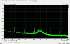
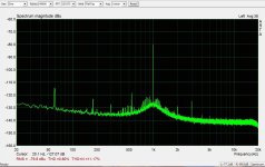
Doing basic research on a new oscillator I would think taking 6 min. of data is no big deal. I was concerned about the post processing time.@SyncTronX -- Here are a couple of screen shots that need some explanation. The oscillator is my HP 339A at 3.3VRMS (600ohms source Z) out into a 600 ohm attenuator loaded by 600 ohms, feeding the active Twin-T notch filter.
The ADC is the EMU-0204, which is quieter than the ADC in the QA-400 by a few dB.
The first shot is -60dB notch, the second is around -80dB. The 2nd and 3rd Harmonics are the oscillator's, relatively independent of the notch depth.
Harmonics above the 3rd do not have a clear source -- I don't think they belong entirely to the oscillator, but I have no way of knowing for sure. If some of them are from the filter or the ADC, I don't know of a way to separate them out. I do have an oscillator with lower distortion, but not a lot lower; if, with it, the higher order harmonics change significantly, what is the source? I'm playing in a sandbox that's full of little gritty things, and the microscopes I have to look at them can't resolve the differences. Microbes? Sand grains? Insect poop?
Attachments
Can't get something for nothing.
It turns out 6 minutes is a big deal, and that's for a single capture. I find anything less than 4 captures is too noisy to be useful. However the time has a real issue. These are RC oscillators and are not that stable. When talking about 16 million bins in 24 KHz that yields bins of .0015 Hz bandwidth. They drift and then during the measurement the signals get spread among several bins. Over 4 measurements the signal has drifted enough that the bins shrink a lot. Aside from taking as much as 45 minutes to get the data this made it pretty worthless.
@rich-EEM, Thanks, for the explanation. If I recall, I think you posted
those earlier, here or another thread. Knowledge is a funny thing sometimes
we don't even "see" it, until we are ready for it...even though we may view
it.
Now I think I understand some of the earlier comments as the QA400
FFT does look slightly different and looks to have more noise, if I recall.
I almost have most of the parts now for doing my HP339A. Naturally
I don't have any of the LT1468s yet, wrong suppler. Not sure how many
I'll need for the various opamp replacements yet.
I want to do a base line before mods for the various 339a sections. I"ll go back over the LONG thread. I also picked up some of the C0Gs ceramics
and wondering about replacing the 0.1ufs in the 339a? Or is that going to
be problematic.
I appreciate the help IDing the LME49740 (LME49710) for the QUAD
opamp buffer/filter after the Oscillator.
Wondering if I should use them on that back vertical board in 339A
that has three of them on it, I didn't know if the originals were all of
the 741 type?
I guess it's time to post it over on the 339A thread.
@Demian, HpW, is there any middle ground between the
1 mio or 16 mio sample bins?
Also, is it possible to get dedicated high end processor just to control
multiple parallel ADCs that would reduce the processing then feed it
into a high end graphics processor? It's kinda what Google did when
they were building search engine processors. They got a bunch of 'puter's
and started hacking out everything they didn't need or wouldn't use to
make them faster.
OR
Think of another way to represent the data? That is what they are doing on
the gaming world for graphics...For example, instead of a smooth gradiant
which would require lots of processing, they used pentagon shape with
different color levels.
OR
Back to originally thought, just get 16 ADCs and parallet them.
OR
Do it with software...as the NETWORK is the computer.
There is increasing returns to scale on this....demonstrated
by the brains over in the EU leading to US going to 128 bit encription.
It shouldn't be a big deal it's only prime numbers...which eliminates
a lot of factors.
Good luck with the 339 project.
There are many steps possible between 1M and 16M but the larger issue is that to get finer frequency resolution to get lower noise you need a larger piece of time. They are reciprocals in effect. Processing is not a big deal, especially today. 16M points is excessive for this. I usually use 512K for high resolution low noise measurements and that is adequate. Coherent averaging is another great solution for lowering noise but you need absolute sync from cycle to cycle. This makes it a problem with a free running oscillator. Locking the oscillator to a synchronous source is a workaround. Doing that without introducing distortion is the challenge.
There are many steps possible between 1M and 16M but the larger issue is that to get finer frequency resolution to get lower noise you need a larger piece of time. They are reciprocals in effect. Processing is not a big deal, especially today. 16M points is excessive for this. I usually use 512K for high resolution low noise measurements and that is adequate. Coherent averaging is another great solution for lowering noise but you need absolute sync from cycle to cycle. This makes it a problem with a free running oscillator. Locking the oscillator to a synchronous source is a workaround. Doing that without introducing distortion is the challenge.
@SyncTronX -- Here are a couple of screen shots that need some explanation. The oscillator is my HP 339A at 3.3VRMS (600ohms source Z) out into a 600 ohm attenuator loaded by 600 ohms, feeding the active Twin-T notch filter.
Hi ! I am in Bangkok now...... Boy is it Really hot here at this time of the year ! I'll never make that mistake again. Anyway --- I see power line harmonics, gen harmonics and the rest is poop from grounding, adc and misc. Other than that, pretty good results.
THx-RNMarsh
Microbes? Sand grains? Insect poop?
Last edited:
@rnmarsh,
Glad you made it in one piece? By the way how tall are you?
I ask because I was amazed heading over to the EU when this
6'8" tall, say 2.1 m sat next to me in coach. I asked him how he
was going to fit it is so crammed up back here...center seat
no exit row...
He just sat down, took off his shoes, brought his knees up to his
chest and wrapped his arms around them and stayed the whole
flight that way. This giant Swede, in his business suit,
in the fetal position full flight. I was surprised he didn't come
down with Thrombosis.
@richard,How's the condo? Fini? Or Last detail stuff on it?
HOT? You said that the last time you were there, hotter now or then?
or do you forget in between what the temps feel like?
It's the Equinox...so does that mean it only gets hotter now and then
you get Monsoons? You hear from Da Hsuan at all?
If you are heading up to Chaing Mai, let me know, I know a stunning
gal who owns a restaurant up there. Uses her hard earned MBA for
Good food. She's starting a chain after proof of concept.
Please send pics, the good, the bad, the ugly.
Harmonics above the 3rd do not have a clear source -- I don't think they belong entirely to the oscillator, but I have no way of knowing for sure. If some of them are from the filter or the ADC, I don't know of a way to separate them out. I do have an oscillator with lower distortion, but not a lot lower; if, with it, the higher order harmonics change significantly, what is the source? I'm playing in a sandbox that's full of little gritty things, and the microscopes I have to look at them can't resolve the differences. Microbes? Sand grains? Insect poop?
Looking at your FFT Spectrums and my 2 cents about:
1. Keep in mind that your microbes are about 1uV or less...
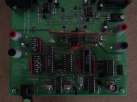
2. around your 1kHz signal, it looks like symmetric modulated jitter signal caused from the main clock. A linear scaled and zoomed spectrum on 1kHz would tell you more about really symmetric and step frequencies.
3. Interconnection may also an issue, rations or ground currents
4. Test whether your microbes relates linear to the input level
5. Or simple ground the ADC input at your notch and look whether you get
Do deal in uV regions it is not an easy task... sometimes you need some special tweaking....
here a picture what I did to get ride of some side peaks of the AKM ADC AK5394 demo board...
Hp
Attachments
@richard,How's the condo? Fini? Or Last detail stuff on it?
HOT? You said that the last time you were there, hotter now or then?
or do you forget in between what the temps feel like?
It's the Equinox...so does that mean it only gets hotter now and then
you get Monsoons? You hear from Da Hsuan at all?
If you are heading up to Chaing Mai, let me know, I know a stunning
gal who owns a restaurant up there. Uses her hard earned MBA for
Good food. She's starting a chain after proof of concept.
Please send pics, the good, the bad, the ugly.
Hi,
It is pretty much finished with the basic things. Needs some art in it.
Ive been to ChangMai several times...... no plans to go up there this trip, though. I'll send some pics soon.
There are only 3 seasons and they are all hot..... this is the hottest season. Around Nov-Feb is the best time, temp-wise. I have a very good location near the top floor (30th) with a townhouse floor plan -- bedroom upstairs and two stores or wall of windows. Fortunately it never gets direct sunlight so it doesnt cook the place. Great view of the city. And it is right beside the sky train to whisk me downtown.
I got this All-In-One HP portable computer (i7) Pretty nice. I ordered HpW software but it didnt arrive before my trip. So, it is something to look forward to when ever I return.
I sent a network analyzer, QA400 and plan to ship a modded 339A over here so i have something to play with between my roaming around.
Got tickets to Kathmandu for their big holiday extravaganza starting Oct.
Now that I have a printer, computer and digital camera here, I can take pictures and email them
Watching a 3D movie on a UHD Samsung TV that is amazing to see. THx-RNMarsh
schematic for fixed 10kHz notch
Hi Dick,
Having built and used your variable design, I wanted to build a fixed notch for 10kHz. I've attached my schematic. I'm using parallel resistors wherein the large value resistor can be swapped out until I get pretty close and then tune with the the 500r trimmer. Have I chosen good values for the caps? And then consequently the resistors? I'm using the dual form of the OPA134 and eliminating the 10db boost. Any and all help would be appreciated.
Ken
Attachments
Hi Dick,
Having built and used your variable design, I wanted to build a fixed notch for 10kHz. I've attached my schematic. I'm using parallel resistors wherein the large value resistor can be swapped out until I get pretty close and then tune with the the 500r trimmer. Have I chosen good values for the caps? And then consequently the resistors? I'm using the dual form of the OPA134 and eliminating the 10db boost. Any and all help would be appreciated.
Ken
Hi Dick,
Re-read the end of your blog on making a fixed frequency notch and am revising the r value up by an order of magnitude and the c down by the same, so the caps will be 1 and 2nf (1000pf, 2000pf). Should have a revised schematic tomorrow. Also will post board layout.
Ken
- Status
- This old topic is closed. If you want to reopen this topic, contact a moderator using the "Report Post" button.
- Home
- Design & Build
- Equipment & Tools
- Build -- Active Twin-T notch filter for distortion analysis